
-
Hello ES! We could use some help to get us past the finish line on building the new knowledgebase for the forum.
Can you donate? Please see our fundraising page. Thank you!
You are using an out of date browser. It may not display this or other websites correctly.
You should upgrade or use an alternative browser.
You should upgrade or use an alternative browser.
TSDZ2 OSF for all displays, VLCD5-VLCD6-XH18, LCD3, 860C-850C-SW102.
- Thread starter mbrusa
- Start date
I had a possibly similar experience recently :I'm not sure what happened to my TSDZ2B. After servicing the motor (oiling and greasing), it started behaving differently. Previously, in Off-Road mode, I could reach speeds of over 55 km/h.
Now, the motor shuts off at 41 km/h in Off-Road mode.
I did a full dissasembly of the motor for maintainance, and since I was at it, I did a hardware calibration of the torque sensor. I had a range of 100 ADC units, and it is now over 200. After I re-calibrated the sensor in the menu, I couldn't get as much power as before, even after increasing assist levels and setting Range Adjust to the maximum. There was no motor cut off though, only less power.
Then I remembered reading that the software torque sensor calibration is useful only in case of a short ADC range, so that users can have a good torque response without having to do a hardware calibration. So I disabled the calibration in the menu and full power came back...
So maybe that's what happened to you in case you touched the sensor ?
docw009
Minor legend
Too much mechanical linkage, I think electrical is easier.Isn't it easier using a small motor + 2 magnets?
WIth a 26" wheel set in the display settings, I have to spin something with two magnets at 260 rpm to simulate 40 mph, and keep it next to the sensor for four days,
Nice that your OSF compatible LCD3 has odometer input. I have several LCD3's and another VLCD5 that I would like to set to the true mileage (I have logs), I guess I'll be pulsing them too.
What max wheel speed do you think you can run the 555 timer at that the display / controller will accept w/o error?Too much mechanical linkage, I think electrical is easier.
WIth a 26" wheel set in the display settings, I have to spin something with two magnets at 260 rpm to simulate 40 mph, and keep it next to the sensor for four days,
Nice that your OSF compatible LCD3 has odometer input. I have several LCD3's and another VLCD5 that I would like to set to the true mileage (I have logs), I guess I'll be pulsing them too.
docw009
Minor legend
Will find out. I think 40 mph should be feasible.What max wheel speed do you think you can run the 555 timer at that the display / controller will accept w/o error?
It's time to release the new version for stock displays, v20.1C.6-update-3.
There were already two improvements to the master version, now I've added another.
Here are the changes:
1 - Fixed the SOC display issue.
2 - Fixed the delay in motor activation/reactivation.
3 - Startup assist, the speed limit can be disabled.
Link in signature.
There were already two improvements to the master version, now I've added another.
Here are the changes:
1 - Fixed the SOC display issue.
2 - Fixed the delay in motor activation/reactivation.
3 - Startup assist, the speed limit can be disabled.
Link in signature.
Hi, everyone! I would like to start by saying that I am quite an amateur in this field, and this is the first time I have ever used a multimeter. So, I apologize if I say something silly.
Motor: TSDZ2 "half B" without throttle and a VLCD5 display
I ordered it from pswpower three years ago, so it's probably an old version and doesn't have any software restrictions.
The Java configurator keeps displaying the error code "device cannot be detected." The most I could achieve was that with the combination of GDN, SWIM, and 5V, on the fourth attempt in STVP, I could read the 3 tabs and save them, but nothing else.
What I tried:
I reduced the version of ST-Link v2.
Tried methods of RST, 3V, battery on/off, in every combination.
I suspected that the contact was not good, so I soldered a conversion cable, but the result was exactly the same. All I can squeeze out of it is the read option, again on the 4th attempt.
I also tried the write command several times, but it won't give in. I tried all jumper combinations and USB port options with the soldered cable.
I'm a little at a loss as to what else I could try. I read somewhere about specifically turning on the vlcd5, but also that it could destroy the entire system, so since I'm not an expert... I didn't want to try that option unless I received specific instructions to do so.
Could the wiring be too long or any other ideas?
Thanks in advance for your help.
Last edited:
docw009
Minor legend
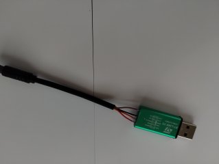
Everyone has seen this picture. The wire colors of your 6 pin extension may differ, but you only need four wires, SWIM, RST, Ground, and Power (which will be 5V or 3.3V) I'm not even sure we need the RST as James Broadhurst in that thread said it's not needed.

When I built a cable, I didn't use RST. Just three wires. Also only used 5V, My cable is 10 cm long, like yours.
However, you have too many wires coming out of the bike. You may get interference from the dangling wires. You also should not be guessing any of the pins are depending on color.
Do a continuity test to the end of the plug and the wires to positively identify which ones are SWIM, ground, and power. Then cut the extra wires off. Mine were cut about 5 cm from the end of the connector,

The display must be turned off. I have accidentally left it on and sometimes the flash worked. Sometimes it didn't, Keep the display off. Perhaps disconnect the bike battery. The USB cable (and your PC) is providing the power to the the TSDZ2 circuitry,
When I built a cable, I didn't use RST. Just three wires. Also only used 5V, My cable is 10 cm long, like yours.
However, you have too many wires coming out of the bike. You may get interference from the dangling wires. You also should not be guessing any of the pins are depending on color.
Do a continuity test to the end of the plug and the wires to positively identify which ones are SWIM, ground, and power. Then cut the extra wires off. Mine were cut about 5 cm from the end of the connector,
The display must be turned off. I have accidentally left it on and sometimes the flash worked. Sometimes it didn't, Keep the display off. Perhaps disconnect the bike battery. The USB cable (and your PC) is providing the power to the the TSDZ2 circuitry,
Last edited:
However, you have too many wires connected to the STM. You may get interference from the floating clock lead that is connected, You also should not be guessing any of the pins are depending on color.
At first, I just tried using three cables many times. I followed the instructions on the wiki. I just plugged them in and used shrink tubing for each one. This only resulted in reading and saving, so I expanded it with RST, but I still couldn't get any further.
Then I started soldering, with only three cables, later soldering the RST and then the other two. Unfortunately, it still didn't work.
All three cables showed a stable 5.01v, so I couldn't determine exactly which one I should use to supply power. I measured the SWIM from the cable coming out of the motor, so I was sure about its voltage, as well as the GND.
I never plug more than 4 cables into the STlink. By variations, I meant that I vary the 5.01v cables the 3/5v pin options, with or without RTS.
docw009
Minor legend
I never plug more than 4 cables into the STlink. By variations, I meant that I vary the 5.01v cables the 3/5v pin options, with or without RTS.
It's the dangling wires coming from the six pin plug that are probably creating signal noise. I suggest cutting off the ones you don't use. They contribute to crosstalk and other electrical gremlims.In that thread I linked, someone said they had to get their wires lengths down to 5 cm to get the cable to work,
I use the ST-LINK V2 all the time using the 4 wire system for years using the RST, GND, SWIM and 5.0V, but did have fun and games to begin with. Firstly I will say is that all these ST-LINKS V2 do not have the connections in the same order RST, SWIM, GND and 5.0V. As I mod the TSDZ2(B)s quite often I will program a bare controller on the table, the only connection being made is to the ST-LINK V2. Are you sure that TSDZ2(B) you have is not a German version with a V2 controller. Doe's the ST-LINK V2 indicate a connection to the PC by powering up and also data being transfer-ed thro' it? Yes my cable soldered to the ST-LINK V2 is 100mm long.
Forgot to say I have used many cables to make up the ST-LINK V2 programing cable and have found there has been variations in the wire colours, you must check the wires colours to the 6 way socket with a multi-meter, even had a cable with all black wires.
Last edited:
I always have connected the STlink v2 flat cable sockets directly to the speed plug, (after first put some shrink tube around it of course), known as "poor man's connection". I only connect +5V, Gnd and Swim..... all these ST-LINKS V2 do not have the connections in the same order RST, SWIM, GND and 5.0V.....
The not used flat cable wires I connect, only on the STlink side, to Gnd.
If I see the Voltages from @Sorriso he measured 5V on the SWIM, which means it should be the flashable controller version.
To see if the connections on the STlink v2 are right, compare what is written on the case and pcb, by shifting the case a bit back to the USB. If there is a difference, use what is written on the PCB.
This means you have a Swim connection. In that case imho you did this with the STVP Gui version..... I could read the 3 tabs and save them, but nothing else.....
Because the Java configurator uses the STVP Cmd version, you must before flashing, shut down the Gui version.
You have also not mentioned that you got some errors.
If STVP does work and SDCC doesn't, or it is the wrong version, the flashing will also aborted.
Last edited:
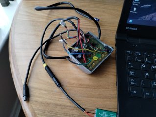
As previous this is all I have plugged in, the laptop, the STlink-V2 and the controller. I do also program the controllers in situ usually everything unplugged but not always if I get an error I always got back to unplugging everything. Note on the STlink-V2 the red indicator is illuminated and will flash / flicker when data is being transfer. I did do a video but it is too big to upload.
Attachments
Flashing stm8's is prone to transmission errors despite being over usb, and this is even w/"better"
tools like a genuine stlinkv3, atleast w/stm8flash, unsure if their own app on windows is perfect.
I just manually retry until it finishes(often the next try).
btw. there's also cheap and simple to make option to the unreliable chinese stlinkv2-dongles for
flashing w/stm8flash made of stm32 bluepill + 4 resistors;

 github.com
tools like a genuine stlinkv3, atleast w/stm8flash, unsure if their own app on windows is perfect.
I just manually retry until it finishes(often the next try).
btw. there's also cheap and simple to make option to the unreliable chinese stlinkv2-dongles for
flashing w/stm8flash made of stm32 bluepill + 4 resistors;
GitHub - stefaandesmet2003/stlinkswim
Contribute to stefaandesmet2003/stlinkswim development by creating an account on GitHub.
github.com
Cable length matters. I once used a 1-meter extension cord for my own convenience, and programming didn't work. I disconnected the extension cord, and programming worked without a problem with 25-centimeter cables.Hi, everyone! I would like to start by saying that I am quite an amateur in this field, and this is the first time I have ever used a multimeter. So, I apologize if I say something silly.
Motor: TSDZ2 "half B" without throttle and a VLCD5 display
I ordered it from pswpower three years ago, so it's probably an old version and doesn't have any software restrictions.
The Java configurator keeps displaying the error code "device cannot be detected." The most I could achieve was that with the combination of GDN, SWIM, and 5V, on the fourth attempt in STVP, I could read the 3 tabs and save them, but nothing else.
What I tried:
I reduced the version of ST-Link v2.
Tried methods of RST, 3V, battery on/off, in every combination.
I suspected that the contact was not good, so I soldered a conversion cable, but the result was exactly the same. All I can squeeze out of it is the read option, again on the 4th attempt.
I also tried the write command several times, but it won't give in. I tried all jumper combinations and USB port options with the soldered cable.
I'm a little at a loss as to what else I could try. I read somewhere about specifically turning on the vlcd5, but also that it could destroy the entire system, so since I'm not an expert... I didn't want to try that option unless I received specific instructions to do so.
Could the wiring be too long or any other ideas?
Thanks in advance for your help.
View attachment 377487View attachment 377488
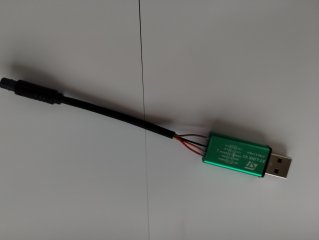
I have the Swim wire in between Gnd wires and a short cable (about 10cm). I use an 1m USB extension cable for connecting my laptop. This never has given any problem.Cable length matters.
docw009
Minor legend
I believe they want the SWIM wire short as possible. The USB side on the STM module is pretty forgiving, up to 3 meters for USB 3.0.
You can see from DGC's picture that the speed sensor cable is already around 6 inches from the circuit board, If you were to google "Maximum length of an SWIM programming cable", you get 4 to 20 inches for an answer. I am happy that mine works.
You can see from DGC's picture that the speed sensor cable is already around 6 inches from the circuit board, If you were to google "Maximum length of an SWIM programming cable", you get 4 to 20 inches for an answer. I am happy that mine works.
Thank you for the replies. To start with, I'll re-solder the cables as short as possible, leaving only the most necessary ones. If that doesn't work, I'll move on to the other possible solutions.
In my case, "suspicion" would be a better word than "sure."
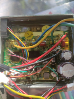
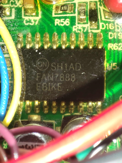
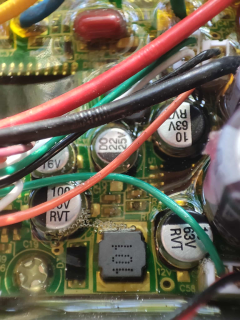
A stubborn damaged screw in a very bad place requires serious surgery, so the flashing project has been put on the back burner. However, since I had to take the whole motor apart, could someone confirm that this is a v1 controller?
Are you sure that TSDZ2(B) you have is not a German version with a V2 controller.
In my case, "suspicion" would be a better word than "sure."
A stubborn damaged screw in a very bad place requires serious surgery, so the flashing project has been put on the back burner. However, since I had to take the whole motor apart, could someone confirm that this is a v1 controller?
Attachments
The other thing I do is with my miniature battery soldering iron is to solder the wires directly onto the ST-Link tabs then check it works, then slide the case back over it (circuit board) and fill the end with glue to hold the wires in place. The pins are easy to get off the board just touch them with the iron and they will just drop off.
Search on this site it has been mentioned before, look here. TSDZ2 - When were the non OSF flashable controllers introduced? I have pulled a motor apart previously and changed a controller.Thank you for the replies. To start with, I'll re-solder the cables as short as possible, leaving only the most necessary ones. If that doesn't work, I'll move on to the other possible solutions.
In my case, "suspicion" would be a better word than "sure."
A stubborn damaged screw in a very bad place requires serious surgery, so the flashing project has been put on the back burner. However, since I had to take the whole motor apart, could someone confirm that this is a v1 controller?
I brought a spare 48V controller from PSWPower in March this year, made sure it was stock from China, it's a V1. Otherwise have ordered from Aliexpress. Still it is hit and miss if a controller is a V1 or V2, did contact TSE (Tongsheng) directly, could not get a straight answer from them a year or so back, all they kept asking for was what make and model was my bike, which is not relevant for a TSDZ2(B) mid-drive.
docw009
Minor legend

Similar threads
- Question
- Replies
- 3
- Views
- 1,194

- Replies
- 4
- Views
- 3,455
- Replies
- 5
- Views
- 2,853
- Replies
- 11
- Views
- 3,731
- Replies
- 8
- Views
- 4,002