You are using an out of date browser. It may not display this or other websites correctly.
You should upgrade or use an alternative browser.
You should upgrade or use an alternative browser.
Turnigy HXT Powered Custom Cruiser Worklog
- Thread starter AussieJester
- Start date
AussieJester
1 TW
Miles said::lol: So, it was only a dream....
Must have been mate...hrmz...then again, i'm still not certain your not
a bot Find it hard to believe a human can be produce so many links and
knowledge on all topics, perhaps it was a glitch in your gfx
KiM
EDITL Damn miles, if you left the pic from the first edit it would have started all over again
OK OK so you caught me out hehehe...i did tell Hyena few days ago i planned to sand and polish it just hadn't gotten round to it
took 5 minutes this morning, took longer to edit the pics actually hehehe...Is it more to your liking now Miles?
enoob
1 kW
thats an awfull photochop miles . how could you defile such a masterpiece
whats next ? kick me signs and wedgiees ? or gay pride stickers on eachothers rides when no ones looking ?
:wink:
AussieJester
1 TW
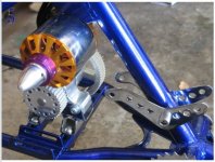
Actually suggested to Hyena with my next Turnigy, the gold anodising will be
re-done with blue, the blue anodising on the ENO freewheel is pretty well identical shade of
blue to the paint! The new scooter wheels have anodised blue centers also, would looks slick i think,
plan on getting some Grips for the bars from ChainReaction that also have some blue anodising
...tiz the little things Miles and whenz theres lots of little things that look good the whole
thing starts to look good i thinkz
KiM
EDIT: haha that would of been along the lines of my reply if he didnt up the above pic onto the ES server, would of edited the original
with a current pic hehehe...
recumpence
1 GW
You guys are so immature. You really need to grow up. I mean, come-on, "My little pony" stickers and pink parts Photo-Chopped onto other's bikes? Give me a break. Like I said, you guys really need to grow up. My little pony is the best you can do? Look at it this way, as least they are horses. Horses are manly enough! A real Man would Photo-chop pink fairies or something truely feminine on another guy's ride! You guys do not even come close. Besides, kick me signs and wedgies? If you were a real man you would go for the POWER-WEDGIE! This involves actually lifting one off the ground by his pink fairy colored underwear (boxers?). :wink:
C'mon, Guys, if you are going to do something, lets really see some effort!
Matt
C'mon, Guys, if you are going to do something, lets really see some effort!
Matt
AussieJester
1 TW
ROFL...see this is why you are the master and we are the apprentices Matt 
Ooooh poor.. poor.. Hyena...
KiM
Ooooh poor.. poor.. Hyena...
KiM
recumpence
1 GW
Oh, my wife suggests "Strawberry Shortcake" as the perfect manly Photo-Chop. 
Matt
Matt
liveforphysics
100 TW
If you haven't all ready, you may not want to toast all those LiPo cells that saw higher voltages.
I've been making some vids testing turnigy 5Ah cells individually, and it took an additional 3.5Ah, and 5.7v to get one to blow!

I've been making some vids testing turnigy 5Ah cells individually, and it took an additional 3.5Ah, and 5.7v to get one to blow!

Thud
1 MW
Luke,
I can't quite make out the meter readings...... :lol:
nothing is more Macho on a hub motor than this crew.
I think the batteries are sold by weight & not volume. Some settling of contents may ocure.
Kim, get us some pics of that assembled bike ya tease.....
There is no way I can wait for the F/G V2 battery manager to see that thing rolling. Just Bite the bullet & charge safely then assemble the "murder" pack & get some video...
This frock war is making me laugh, I still haven't picked sides yet. My bike has a frock, but my mountain board is getting a turnigy, does that mean the board is just a beard and I'm a closet f.a.g.s or am I just an experimental m.e.n.s 
Your bike is really coming together well. I love the chunky rubber on the rear. I seriously hope you take it to a few shows and park it between some smoking customs. You'll be one of the most popular bikes there.
I know you're not a pedaler, but have you abandoned them completely? Even if you don't use them, it'll be cool to say you have bicycle that can burn rubber.
AussieJester
1 TW
liveforphysics said:I've been making some vids testing turnigy 5Ah cells individually, and it took an additional 3.5Ah, and 5.7v to get one to blow!
Yes i still have them Luke packed in a box, more than half are on 5v the rest over 4.5 prolly 6-7 cells the rest are 0v
It is indeed good to know that lipos these days are ALOT more robust than the ones of several years ago isn't it!
They obviously still burst into flames but man you really need to push them riiiight over their limit to get them to do so!
I have 6 fresh cells ready for the bike (2 due today will make 6 anywayz) I'll be ordering another 3 today (pay day woot)
so ill have the 9 required for 66v 15ah as per our agreement
Thud...'SAVED' image to pc hehehe poor poor Hyena, you will see this again you have my word hahaha... The bike is fully assembled
now except for the electrics side of it Thud (oh and the brakes waitng on new hose for the hydraulic Juicy 7s)
its not just the bms i haven't got a sensored controller to use i am happy to coble together the batteries together and
wait for the BMS to be finished but still leaves me with an unpainted battery enclosure, all i need is specs on plugs and leds
or if i display panel is needed and i can do this and send it for paint but i haven't been given these details as yet :-(.
I would also prefer to have the Infinion and halls setup rather than going back with the hv110 so I ordered another 12fet Infineon
from Lyen hopefully it will be here in the next week I'm at the mercy of others Thud i have done all i can do at this point mate
patrickza...yeah i hope to get it to a couple of shows, Matt.P has shown his bike at several, when they come around
again i will see if Matt will take me and the bike along too, he has a trailer hehe...and a car...
and a drivers license...i have none of these LoL Having one of each a frock and a non frock setup makes you a
bi-e-biker These are confused individuals that swing both ways F.A.G.S to M.E.N.S Just quietly
i think Hyena wishes to be a bi-e-biker to, we is working on the conversion process
Cheers guyz..
KiM
EDIT: OH and yes patrickza the pedals are on the bike and will remain that way and operable, it is fully functioning bicycle.
AussieJester
1 TW
John in CR said:Ok, so it's a fully functioning bicycle, but when is it going to be a fully functioning e-bike? I guess all this non-frock stuff is just for show, not for go. If the thing actually ran maybe we could give a pass on the pink/magenta.
Perhaps try reading the text John? i have explained several times why it isnt going at this time and it has nothing to do with the drive system. It has run perfectly well prior to the break down and would have continued to do so if i didn't give a rats ass about how it looked, like your good self John
Classy stuff i agree John, but i still prefer nuts and bolts welds and epoxy over duct tape.
KiM
AussieJester
1 TW
So i went to buy the 3 remaining 22v 5000mah Turnigy pack i require to make a 66v 15ah pack, turns out HK is out of them ...typical.
After seeing El_Steak's awesome battery leads-->

I thought i might knock up something similar, actually something pretty much identical haha-->

Hyena...i hear you wondering, they were ~11 bucks each for the fuse
they are in the car audio section at Jaycar they come in 50-250amp
all are same physical size.
I picked up 2x200amp fuses from JayCar (i should of bought 3 and done a 66v setup i guess but with only the hv110 controller i decided i would stick with 44v, ill pick up another fuse when i have the Infineon and likely make another 4 into one setup and go with 88v too make Lukez proud hehehe
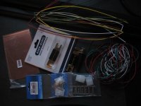
I have also bought some assorted coloured oober thin wire and heatshrink a few connectors YES they are for the halls in the tunigy
I bought some silicone adhesive also, yup, im going for an internal 120 degree setup, figured i can have all the halls inside the motor
for when the Infineon turns up and then it will :: fingers crossed: just be a case of working out the connections to the controller. All the hall wiring can be done sleeved and run with the 3 motor wires for now.
I shall start work on this tomorrow and report back...OH...my extra 2 packs from HK that SHOULD of been here according to tracking 2 days ago still didn't turn up today, seeing its Easter long weekend i wont see them till at least Tuesday i wouldn't think.
EDIT:
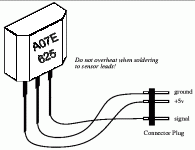
OH..GWhy Burtie..Luke...Miles...BigMoose...enoob...? anyone..am i right to asume this is the correct wiring for the halls

And ...is it the'done thing' to simply connect all the positive and negative
legs on the halls together and run a single "+" &"-" wire from one of the hall sensors or is it more acceptable to run 3 wires from each hall and join them up 'externally' before plugging them into the controller ( I noticed this was the method you did on yours GWhy?) As you know i have never done this nefore so any tips would be appreciated...
Back soon
KiM
After seeing El_Steak's awesome battery leads-->

I thought i might knock up something similar, actually something pretty much identical haha-->

Hyena...i hear you wondering, they were ~11 bucks each for the fuse
they are in the car audio section at Jaycar they come in 50-250amp
all are same physical size.
I picked up 2x200amp fuses from JayCar (i should of bought 3 and done a 66v setup i guess but with only the hv110 controller i decided i would stick with 44v, ill pick up another fuse when i have the Infineon and likely make another 4 into one setup and go with 88v too make Lukez proud hehehe
I have also bought some assorted coloured oober thin wire and heatshrink a few connectors YES they are for the halls in the tunigy
I bought some silicone adhesive also, yup, im going for an internal 120 degree setup, figured i can have all the halls inside the motor
for when the Infineon turns up and then it will :: fingers crossed: just be a case of working out the connections to the controller. All the hall wiring can be done sleeved and run with the 3 motor wires for now.
I shall start work on this tomorrow and report back...OH...my extra 2 packs from HK that SHOULD of been here according to tracking 2 days ago still didn't turn up today, seeing its Easter long weekend i wont see them till at least Tuesday i wouldn't think.
EDIT:
OH..GWhy Burtie..Luke...Miles...BigMoose...enoob...? anyone..am i right to asume this is the correct wiring for the halls

And ...is it the'done thing' to simply connect all the positive and negative
legs on the halls together and run a single "+" &"-" wire from one of the hall sensors or is it more acceptable to run 3 wires from each hall and join them up 'externally' before plugging them into the controller ( I noticed this was the method you did on yours GWhy?) As you know i have never done this nefore so any tips would be appreciated...
Back soon
KiM
liveforphysics
100 TW
AussieJester said:And ...is it the'done thing' to simply connect all the positive and negative
legs on the halls together and run a single "+" &"-" wire from one of the hall sensors or is it more acceptable to run 3 wires from each hall and join them up 'externally' before plugging them into the controller ( I noticed this was the method you did on yours GWhy?) As you know i have never done this nefore so any tips would be appreciated...
Back soon
KiM
That's the way I've always seen it done. Tie all the + together, the - together, then run the output's A, B, C. This means to run 3 hall sensors it takes only 5 little wires. It is critical not to mix - or + inputs to any other pins on the hall sensor, they die inside, and it's hell trouble shooting them.
AussieJester
1 TW
Hyena said:AussieJester said:Hyena...i hear you wondering, they were ~11 bucks each for the fuse
You overpaid my nigger!
You can get em for $2 ea delivered HERE on ebay. I guess if you wanted them in a hurry though you had to pay the premium.
Well of course everything is cheaper on the net
at least have a ride on the bike over Easter. (those ones you linked are also 100amp not 200amp)
Cheers Luke shall make sure i dont mix them up, i got different colour wires to help
keep things in order
KiM
Hyena
10 GW
Bah you don't need fuses anyway, I thougth you were gangsta. I bet you bought pink ones 
BTW did you source the halls locally ? I need to troubleshoot my spare frockie and I suspect it may be a hall issue
BTW did you source the halls locally ? I need to troubleshoot my spare frockie and I suspect it may be a hall issue
AussieJester
1 TW
Hyena said:Bah you don't need fuses anyway, I thougth you were gangsta. I bet you bought pink ones
Yeah i know but it makes for a neat 4 into one hookup i looked for thin copper or
brass plate to use but there was none at Bunnings and the thinnest i have is ~3-4mm bit too chunky
to solder too.
BTW did you source the halls locally ? I need to troubleshoot my spare frockie and I suspect it may be a hall issue
Nope enoobz sent me 5 of them so i have enough for a motor and a couple of spares, JayCar don't have the right halls
i forget what the ones are they sell but GWhy said they ain't the ones needed when i linked him up. You have a credit card
dont you? Heaps of places online to get them i just couldnt find one that did paypal hence enoob helped me
out.
KiM
gwhy!
100 kW
AussieJester said:And ...is it the'done thing' to simply connect all the positive and negative
legs on the halls together and run a single "+" &"-" wire from one of the hall sensors or is it more acceptable to run 3 wires from each hall and join them up 'externally' before plugging them into the controller ( I noticed this was the method you did on yours GWhy?) As you know i have never done this nefore so any tips would be appreciated...
Back soon
KiM
Yes all +'s together and all -'s together, I connected all my + and - together as they came out of the can on my large motor this was to make it less bulky inside the motor, But as soon as the wire exit the can they are joined together so you will only have one + wire and one - wire going back to the controller along with the 3 signal wires, as Luke have said 5 wires total to the controller. Twist the 5 wires together and try to keep them as short as possible when they go off to the controller.
AussieJester
1 TW
gwhy! said:AussieJester said:And ...is it the'done thing' to simply connect all the positive and negative
legs on the halls together and run a single "+" &"-" wire from one of the hall sensors or is it more acceptable to run 3 wires from each hall and join them up 'externally' before plugging them into the controller ( I noticed this was the method you did on yours GWhy?) As you know i have never done this nefore so any tips would be appreciated...
Back soon
KiM
Yes all +'s together and all -'s together, I connected all my + and - together as they came out of the can on my large motor this was to make it less bulky inside the motor, But as soon as the wire exit the can they are joined together so you will only have one + wire and one - wire going back to the controller along with the 3 signal wires, as Luke have said 5 wires total to the controller. Twist the 5 wires together and try to keep them as short as possible when they go off to the controller.
Yes i follow the number of wires etc i was just curious as to the best method of doing it i.e inside the can or after all the 9 wires come out of the can then join you the pos/negs...shall wait till i pull the motor apart tomorrow and make the decision then when i see the room i have to play with, having 3 wires from each
hall and joining the "+" & "-" wires up when all wires have exited the can might make things lil bulky and messy, something i wish to avoid hence my decision to go with internal setup over the external, if i loose a .02 percent efficiency no big deal if it looks neater.. I have my fingers crossed the halls are the right ones they are different model to what you and Burtie have used GWhy, i think enoob said they weren't
rated for quite as high a temperature? My motors doesn't get too hot to not be able to hold a hnd on it continuously so i doubt heats will be a problem.
Thanks again for your input GWhy always helpful cheers
KiM
gwhy!
100 kW
Hi AJ,
You could connect them inside the can but due to space I thing you may find it a bit easier to join outside. Solder your wires onto the halls before you put them in the slots ( if your connecting them inside the can this will make it tricky getting the correct length of wire between the halls and the wire may not sit right out of the way of the spinny bit )
You could connect them inside the can but due to space I thing you may find it a bit easier to join outside. Solder your wires onto the halls before you put them in the slots ( if your connecting them inside the can this will make it tricky getting the correct length of wire between the halls and the wire may not sit right out of the way of the spinny bit )
AussieJester
1 TW
gwhy! said:Hi AJ,
You could connect them inside the can but due to space I thing you may find it a bit easier to join outside. Solder your wires onto the halls before you put them in the slots ( if your connecting them inside the can this will make it tricky getting the correct length of wire between the halls and the wire may not sit right out of the way of the spinny bit )
Quite possibly as i also want to sleeve all the wiring starting at the halls, will protect the wires from any heat
over extended periods. Shall see how it goes, will pm pics through to you either way GWhy ..cheers mate
KiM
enoob
1 kW
page 11 of this document my good man and you are looking for the pin outs of the UA package. i believe you have it correct from left to right 1= power 2= ground 3= signal
http://www.allegromicro.com/en/Products/Part_Numbers/3230/3230.pdf
I had concerns obout overheating the LH units i used (very small tabs) meant for different mounting than i ended up using. next time ill be using the UA's
i tested them after soldering by hooking them up to my volt meter and running magnets past them to see if they were still open/closing the circuit .
Similar threads
- Replies
- 0
- Views
- 161
- Replies
- 10
- Views
- 1,839
- Replies
- 13
- Views
- 759
- Replies
- 6
- Views
- 673
- Replies
- 29
- Views
- 5,232


