Who have already blowed their Crystalyte controller here?

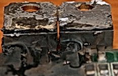
As I recall, most of the failures happened in a group around 6 months ago. I remember Maytag's 72 volt controller blew at way less than 72 volts. At that time, it was theorized there was a bad batch of FETs going around, or a run of controllers was produced without adequate insulation around the FETs. Even if there was a bad batch, the good batches aren't exactly top quality.

I purchased my 72v35a controller almost a year ago. For most of that time I've run it at 84 peak volts, 80 volts average without problems, without any overheating, or signs of problems. Still, I look forward to replacing the stock FETs with more reliable, more efficient, lower resistance IRFB4110s (and might-as-well increase that current limit while I'm at it... :D ).
 
Enclosed are pictures of the controller with blew FETS inside. I bought two brushed Crystalyte 48V 25A DC controllers. The one on the left is blew by overvoltage with 72V (6 X 12V 12aH) batteries. Does anyone know how to get it fixed? I have already tried to replaced the FETs by still unable to get the motor spin. The voltage regular is still working since the red LED is light up when I power the controller on. Any ideas? Thanks!
[/img]
 

Attachments

  • 2.JPG
    2.JPG
    78.2 KB · Views: 2,769
  • 3.JPG
    3.JPG
    108.8 KB · Views: 2,772
  • 4.jpg
    4.jpg
    17.9 KB · Views: 2,772
  • 5.JPG
    5.JPG
    69.2 KB · Views: 2,767
  • 7.JPG
    7.JPG
    67.6 KB · Views: 2,768
  • 8.JPG
    8.JPG
    78.5 KB · Views: 2,771
About the regulator, it normally produce the 12 or 14V the hall sensor need and also supply the other 12v IC. But If it's same on your controller, (like mine, a 72v35A) you should also have a small voltage regulator (like a small transistor) that take the 12V and convert it to 5V for the throttle and other part of the circuit. If it is blown, nothing will work. So check for a 78L05 labeled transistor and check if one pin is at around 12V and the second on the ground 0V and the last at 5V. if you dont have, i'm pretty sure you need to replace it. it's less than 1$.

Doc
 
To check the 5V regulator, see if you get 5v on one of the throttle pins.

The other thing that usually blows is the FET gate driver.
If you're lucky, it will be just the resistors. Measure across them with an ohmmeter (power off). If they measure way higher than the marking indicates, they're toast. I can't see the marking in the pic clearly. They're usually between 10 and 100 ohms. If the resistors are marked "100", that's 10 ohms.

If you're not lucky, the gate driver transistors might be blown as well. When they go, there's usually a short across two of the leads. Use an ohmmeter to measure all combinations of the 3 leads. No shorts is not a guarantee that they still work. An oscilloscope would be the best way to see what's going on.
 

Attachments

  • Blown FETs 2.jpg
    Blown FETs 2.jpg
    67 KB · Views: 2,746
Dear Fechter, thank you very much for point me to the right direction. I have actually done exactly what you have suggested. The result besides the 2 blew FETS are 2 resistors on R17 & R18 connecting to the FETs have much higher resistance than 10 Ohms. Also, the diode (Z2) & transister (T1 & T2) have shorted legs. However, I could not get the part numbers of the the diode and the transisors for replacement. Can you tell me the exact part numbers for them? I appreciate your and everyones' helps! See image below.
 

Attachments

  • T1-T2_edited.jpg
    T1-T2_edited.jpg
    20.8 KB · Views: 2,693
  • whole_board.gif
    whole_board.gif
    477.6 KB · Views: 2,191
I don't know what the exact part numbers for those transistors would be. It's not critical, however. They are a complimentary pair (one NPN, one PNP) and should be rated for 500ma and as much voltage as the rest of the controller.

It may be possible to use larger TO-92 transistors as replacements.

The diode is marked Z2, which leads me to think it's a zener diode. It might be to limit the gate voltage, which should be somewhere around 12v.

See the attached partial schematic. The transistor numbers given are used on the 35A brushless controller, so they should have the right ratings. The basic configuration should be similar.

It would be best to find some SOT package transistors that fit directly in the spot.

It might take some searching around on DigiKey or somewhere to find something that would work.
 

Attachments

  • Brushless Controller Output stage 2.jpg
    Brushless Controller Output stage 2.jpg
    6.1 KB · Views: 2,599
Dear Fechter! Thank you for the diagram you provide. I happened to own an electric scooter and yesterday I opened it up and found a controller with 2 transistors you mentioned, I then tried both and narrowed down the problem is with a burned out transistor on T1. I have replaced with 2N5401 PNP and the bike come alive again! You are awesome and you are the God on the Crystalyte controllers! The my bike, scooter, controllers below:
 

Attachments

  • 1.gif
    1.gif
    409.1 KB · Views: 1,767
  • 2.gif
    2.gif
    336.2 KB · Views: 1,772
  • 5.gif
    5.gif
    294.4 KB · Views: 2,531
Good news.
Good idea with the jumper wires. I does look like a tight space.

That scooter looks deadly. I guess it's slow, so not too deadly.
Did the scooter blow a FET at the same time as the driver transistor?
 
I think I screwed the controller again after I feed it with 72V. Technically, I have replaced two 75V FETs with two 100V FETs and the 2N5401 PNP. The motor right keep spinning event without the grip throttle attach to the controller. The throttle was fully functionally @ 36V and prior I feed it with 72V. Now even at 36V the motor still spins with or without the throttle. Can you tell me what is wrong now? What things would have damaged on the circuit board? I do not see any visual damage this time. I appreciate your help again. As for the scooter, it is not functional right now because I took a transistor out of it from the controller for the bike. The controller was work again once I put the transistor back.
 
Yikes,
it sounds like one of the FETs shorted drain to source. With the power off, you can measure resistance between the battery negative and the motor negative. If it reads near zero, the FET is most likely shorted.

Something in the driver circuit could have shorted also.

You could try measuring the gate voltage powered up. The motor can be disconnected. With no throttle, the gate voltage should be near zero. Measure with respect to battery negative.

Removing the FETs (again) you can tell for sure.

Even though the FETs might be rated for enough voltage, at higher voltages you might be exceeding their current rating. I hate it when that happens.

You might consider IRFB4110's, but it's hard to say if the driver will properly work with the higher gate capacitance. It usually does.
 
Fechter, I have found the problem after burning out 4 FETs on the same spot. After I did a research of the internal diagram on the FETs & the 2N5401 PNP, it turns out the collector & emitter leads were flipped on the 2N5401 and sent out excessive voltage to the FET (the one close to the T1 > 2N5401 transistor). I was surprise the FET can handle up to 36V without getting destroyed. Anyway, it was a good learning experience & fortunately the FETs are inexpensive. An order of FETs are being ordered including the IRFB4110 that you have suggested. My goal is run 72V brushed 20A controller on the ebike. I have also a FET + higher amp rectifier to beef up my 20lbs scooter with a 140W DC motor. It would be interesting to run the scooter motor with 60V (5 x 12V batteries). Thanks again for your help on the controller issue!
 
So far have blown two 72V 35A controllers. One had two "phases" of FETs blown. Replaced them and it didn't fix it so I gave up. I just blew a second one. Neither one was abused other than being connected to 72 volts (well, 84 volts for the fully charged pack.)
 
billvon said:
So far have blown two 72V 35A controllers. One had two "phases" of FETs blown. Replaced them and it didn't fix it so I gave up. I just blew a second one. Neither one was abused other than being connected to 72 volts (well, 84 volts for the fully charged pack.)

Like to know a bit more detail how they are blown.
 
billvon said:
So far have blown two 72V 35A controllers. One had two "phases" of FETs blown. Replaced them and it didn't fix it so I gave up. I just blew a second one. Neither one was abused other than being connected to 72 volts (well, 84 volts for the fully charged pack.)

Bummer. My unmodified 72v 35a crystalyte controller has worked flawlessly at 84 peak volts for over a year and 2000 miles now.
 
Like to know a bit more detail how they are blown.

One blew upon connection of charge voltage (84 volts) to the system. Controller was OFF. This one was dramatic - smoke, crackling noises etc.

The second blew upon application of throttle. I have a bike wired to allow either 36 volt operation (parallel) or 72 volt (series) operation. I stopped at a light, turned off the 36 volt breakers, turned on the 72 volt breakers and observed the meter indicate 81 volts. I pedaled a bit, then added throttle, and felt at least one phase blow out (i.e. it shorted.)

Anyone have any recommendations on which FETs are best for replacement?
 
IRFB4110 are highly recommended. Lowell is running them at slightly over their rating, with no smoke so far 8)

I'm not aware of any that have blown other than connecting the batteries backward.

Interesting that one blew while switched off. I think this is rare.

Most failures occur like second one. At higher voltages I think the stock FETs just can't handle the current or dissipation (not sure which one). Most failures happen at over 48v.
 
fechter said:
I'm not aware of any that have blown other than connecting the batteries backward. Interesting that one blew while switched off. I think this is rare.

Yeah, and for a while I had myself convinced that I HAD connected at least the charger backwards. But the battery fuses were intact, and I can't believe the batteries (a 72 volt lead acid pack) would let a 3 amp charger reverse-bias the system.

IRFB4110 are highly recommended.

OK, thanks. Will check the gate drive resistors as well. Hopefully nothing else went south.

The biggest problem reworking this thing will just be getting access. There were half a dozen wires haywired on the controller board when I got it, and I added another five for the Cycle Analyst meter.
 
When i blew my controller (a stock 72V start immediate 35A) there was maybe two or three reasons:

First, i've already reversed the battery polarity connector to the controller and the 40A fuse blew. I installed a new one and curiously, that worked well :( .. no probelm to go to my job, climbing little hill..etc...

The second bad luck happened when i just wanted to show my ebike to my friend. One minute before, the charger just have terminated to charge my sla AND THEY WAS FULLY CHARGED AT 90V...! when i pushed the throttle, just to show the quick start and the torque, . I heard : "tik".. inside the controller, the fuse blew again... and you know the rest... :(

I repaired it with the the bulletproof option: a set of 12 new IRFB4110 plus 4 spare! .. in case where it would blow again..
:wink:

Now, regarding what it happened before and after talking to fechter and Justin that are a have a great knowledge with those, we concluded that it's probable because some of the 12fets inside the controller blown or was just more sensitive and risky with more current demand.. They still worked for a moment(when i goes to my job).. and the time i fully charged my sla to 90V gave those too much stress and the damadged(but working) fets blew first and the rest follow them in a fraction of a second due to multiple short to pos and neg phase...

i've blew ALL the gate drivers, 40% of the gate resistor, blew the 14V regulator the 5V regulator too and all the 2n5401 and 2n5551. By that, the 90V goes directly to the PWM and the Phase modulator IC and they blew too...

The only component that havent blew was the 100V caps, all the resistor that are higher than 1k and some to-92 transistor :lol:

A REAL BLOW UP! :evil:

to help me, Justin sent me 3 slightly broken controller board and i began to build a new one with those. I used a set of IRF4710 and other 55V rated fets and run 2 month with those at 36V... :? ... waiting to receive my 16 bulletproof fets! :twisted:

then i installed those and removed all the 4710, irfz44 and other..

Now i have a "bulletproof" controller with:

4 spare 4110
8 spare 4710
9 spare 3205 55v rated
4 irfz44 60V rated

I've tested those at 84V sag down to 77V 2 days ago WITHOUT ANY PROBLEM !! :wink: :D

I've heard that they can handle like 92V... ?

Doc
 
Mine blew, It ran for a week; I sent it back and got it replaced, (3 weeks) now something else is broken. After a day. I ran it last night for a test fine for 3 miles, got up this morning and it broke in my driveway. Late to work. :roll:

My cheap WE kit never had such problems.
 
Brucey said:
Mine blew, It ran for a week; I sent it back and got it replaced, (3 weeks) now something else is broken. After a day. I ran it last night for a test fine for 3 miles, got up this morning and it broke in my driveway. Late to work. :roll:

My cheap WE kit never had such problems.

Your last one blew because you stuffed bullet connectors into powerpole connectors on the motor leads -- one got loose and shorted against the others.
http://endless-sphere.com/forums/viewtopic.php?t=1871&start=15
What do you think happened this time?
 
I still see no problem with that original connection, the connection was secure but I'll go ahead and take the blame for it. But this time I'm not sure. I got ahold of some powerpoles and made sure to use them, I'm actually thinking it is a problem with the motor this time. It's not got the same symptons as before. I'll have to check it further when I get home.

I didn't touch it when I parked it last night and it ran fine, now its dead as can be from going up my driveway. Go figure.
 
Damn.

motorwire.jpg


:roll: :roll: I wonder if it grounded to the bike? It had rotated in the fork and was cut into; Going to try to repair the wires I guess. Hope the insides didnt go boom. Didnt think I'd need a torque arm at 48V.
 
Brucey said:
I wonder if it grounded to the bike? It had rotated in the fork and was cut into; Going to try to repair the wires I guess. Hope the insides didnt go boom. Didnt think I'd need a torque arm at 48V.

So the axle spun, damaged the dropouts and tore the wires?
 
Actually, the drop outs dont seem to be damaged, the axle had spun slightly and mangled the axle threading, cut the wires, but now that I've looked at the drop outs they look to be fine. A few scratches but not bent or anything.
 
Back
Top