
Eastwood
100 kW
- Joined
- Jan 13, 2021
- Messages
- 1,480
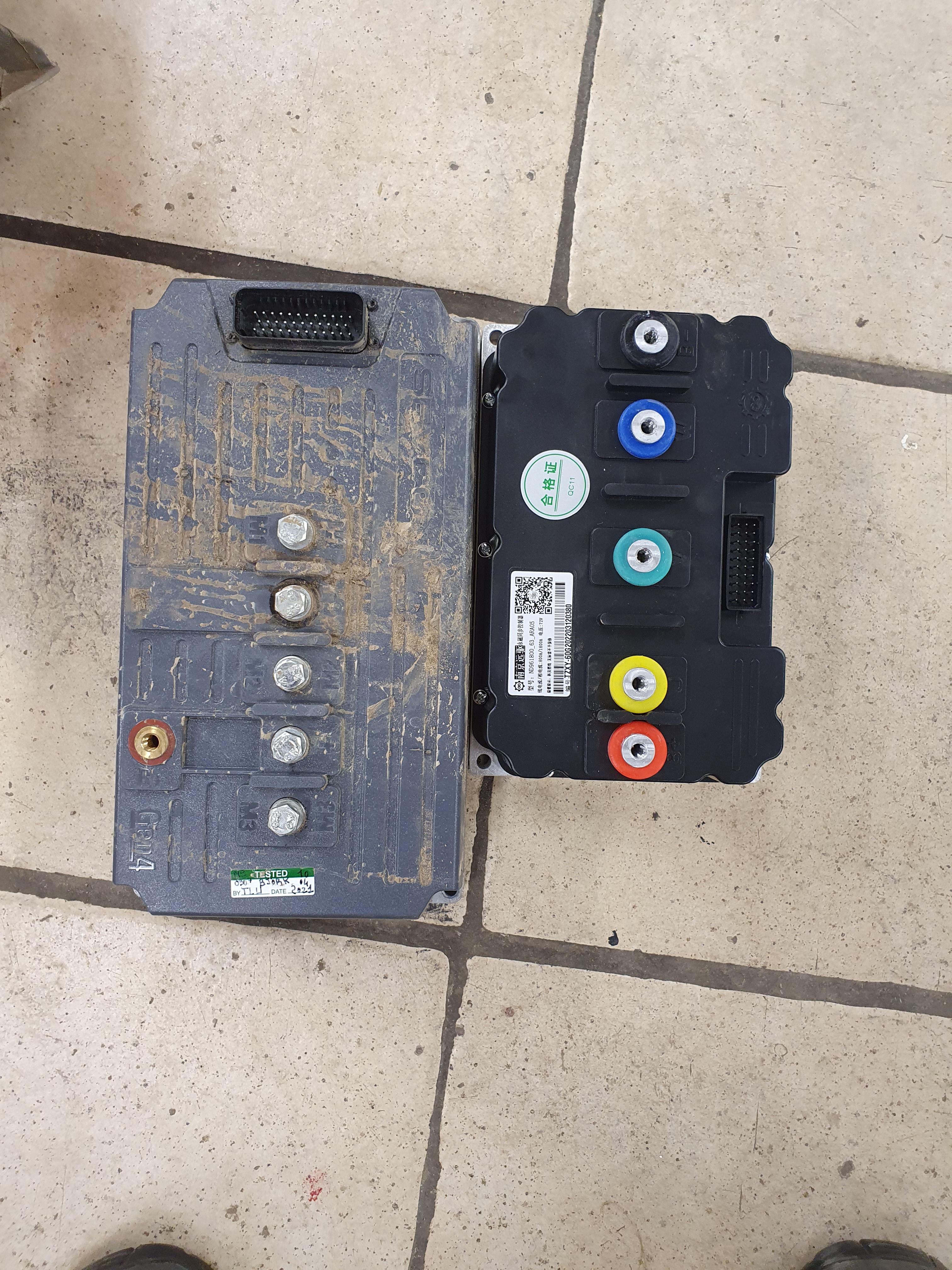
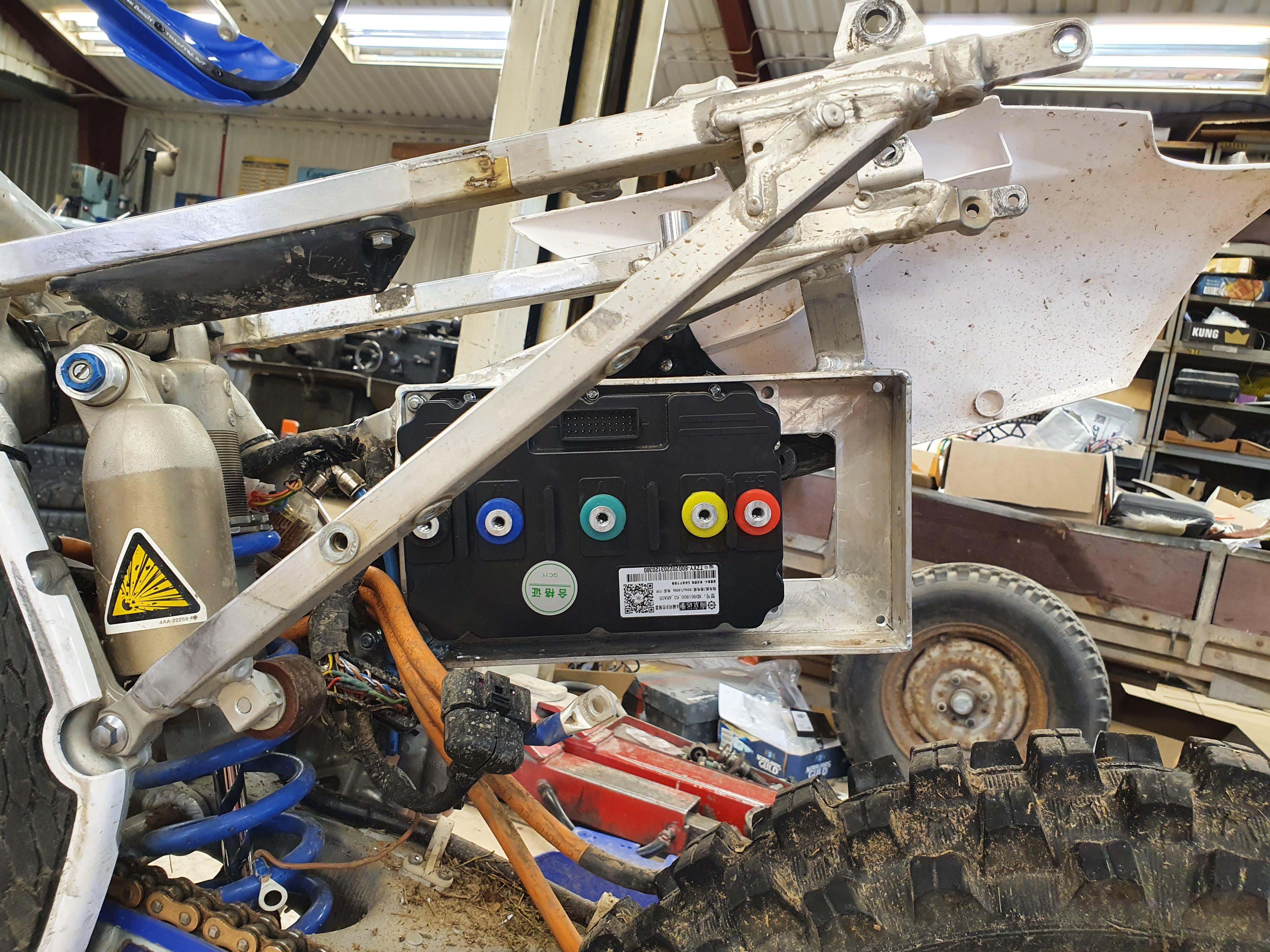
j bjork said:Finally some progress, I got a motor
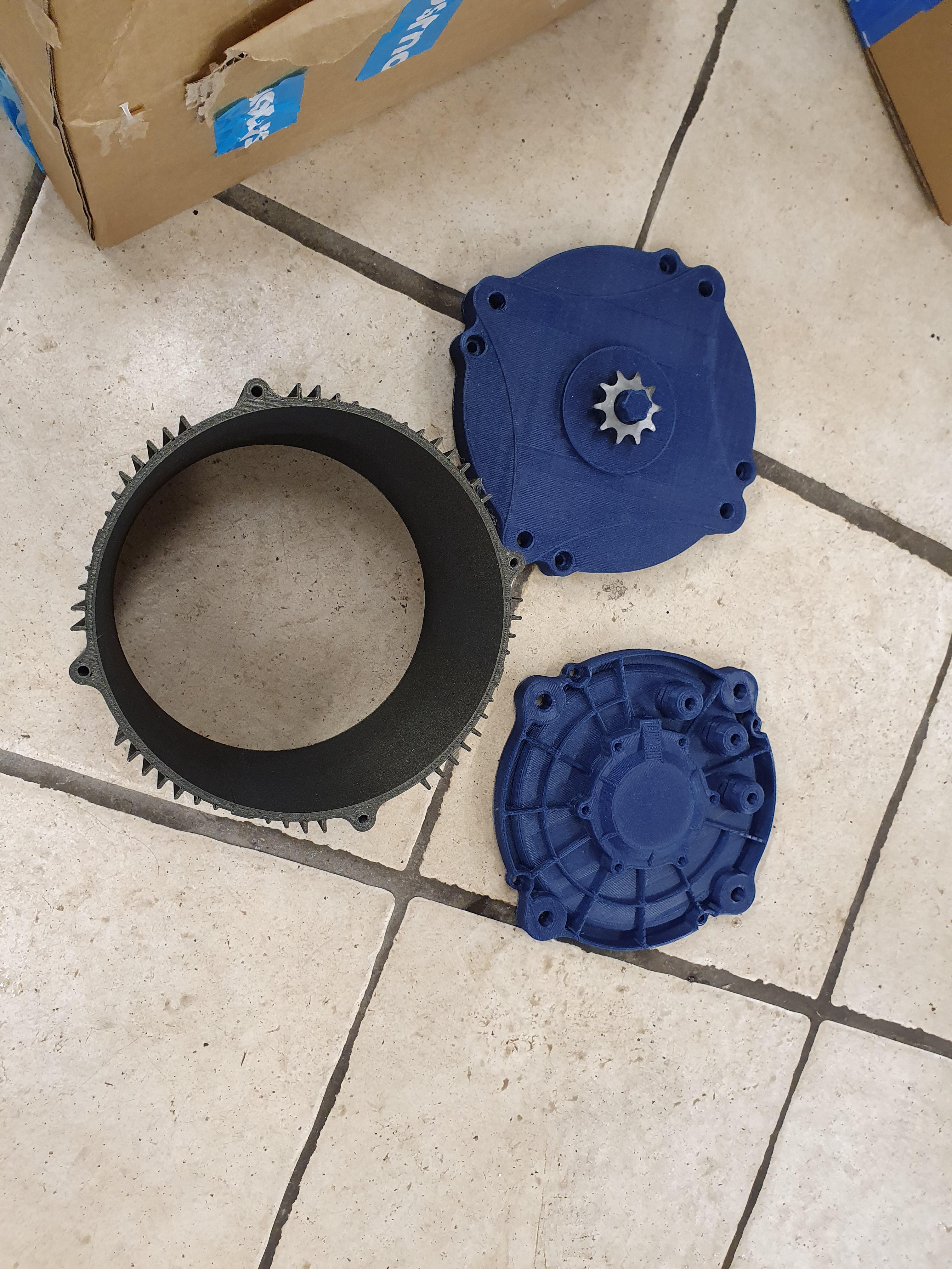
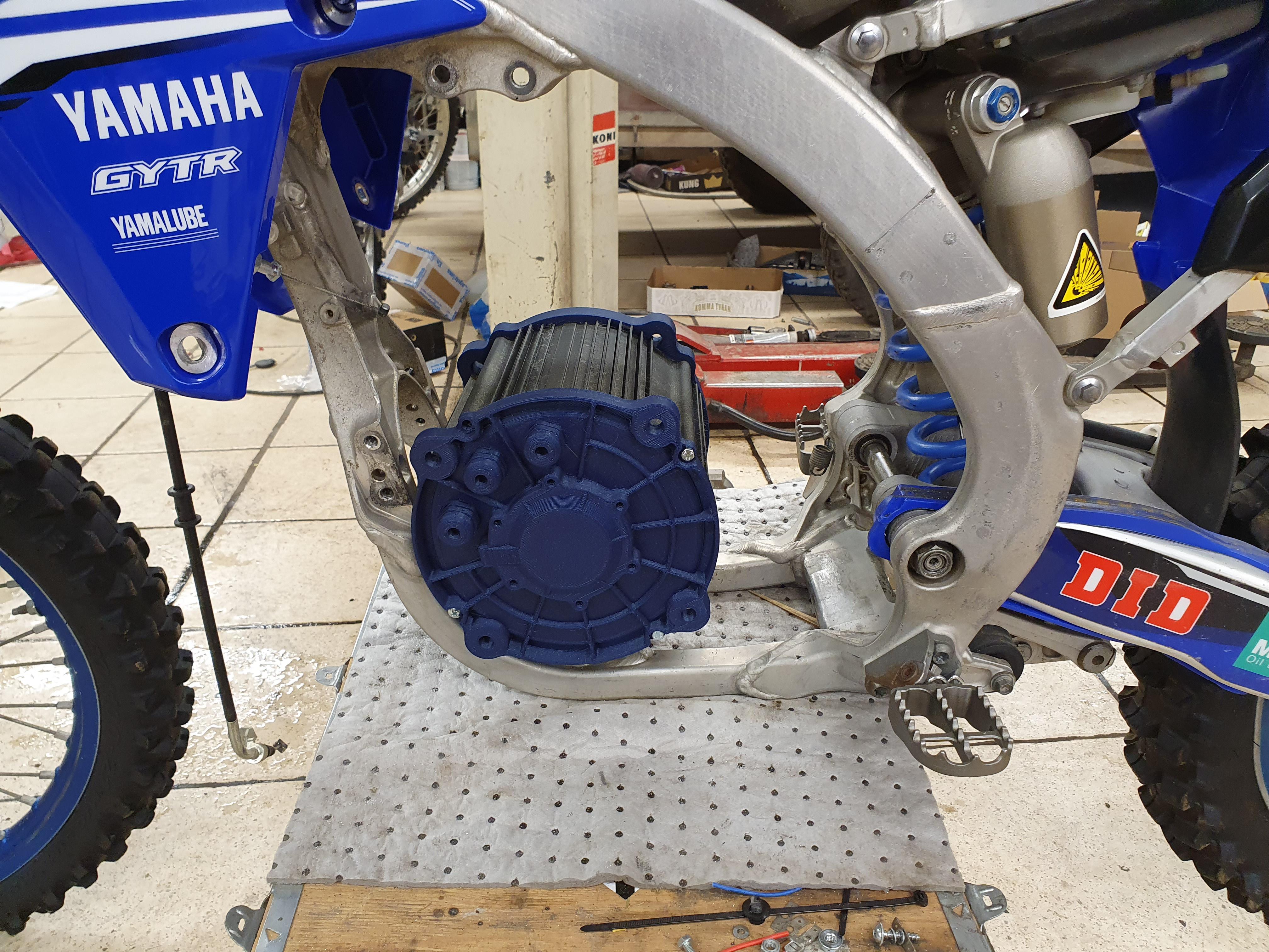
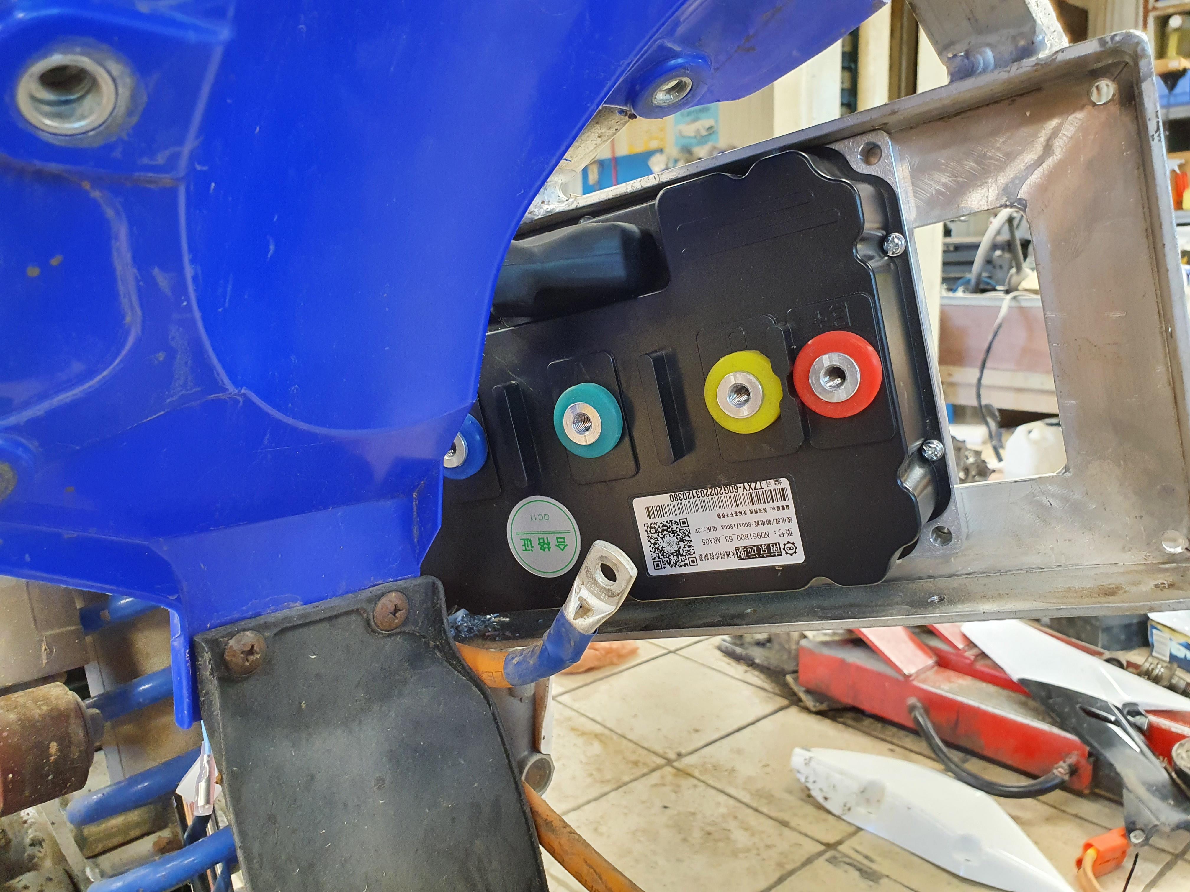
Hmm, it is kind of big..
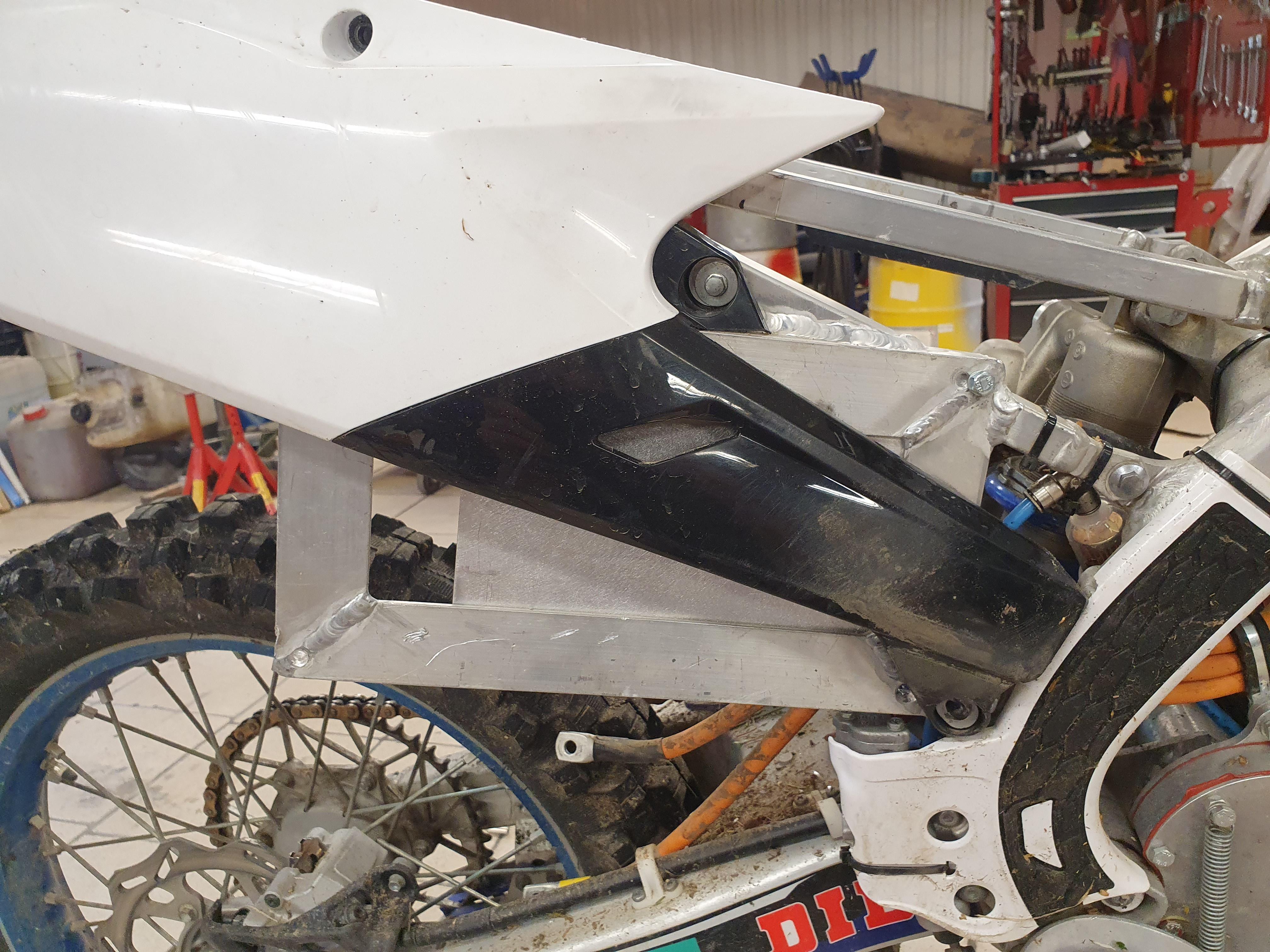
Hi j bjork, could you share the dimensions of the QS 180?
j bjork said:Finally some progress, I got a motor
Hmm, it is kind of big..
Ianhill said:You could try shoving aload of little sandbags in the front wheel keep it down under throttle so you can get your launch but it will be tuned in a way that without them its going to lift.
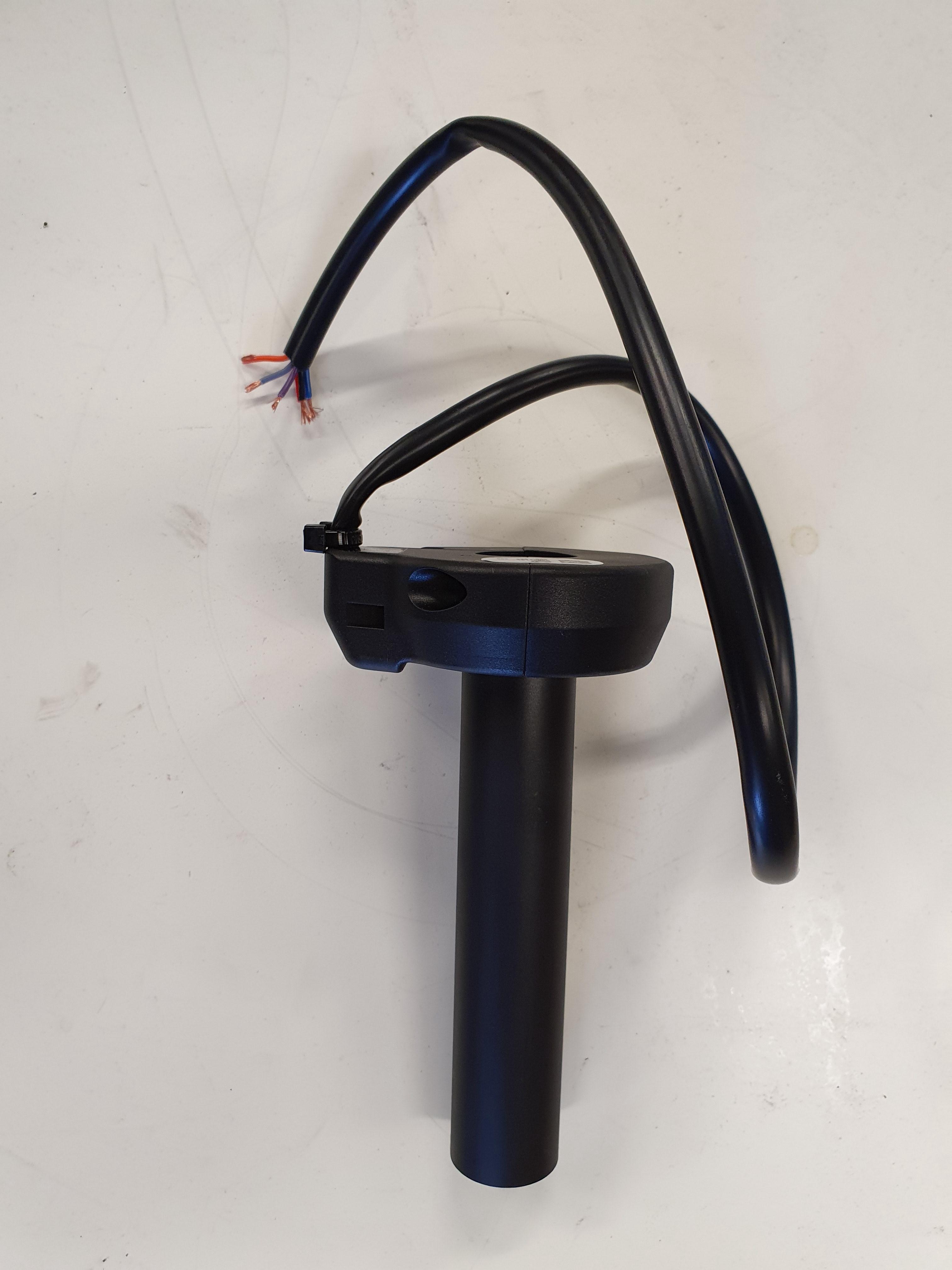
Anti wheelie devices are simple enough to fit to anything with a electronic twist throttle if thats something you could be into for maximum launch speeds.
 . I plan on having a play with the controllers rs485. If you can reprogram while running you can probably get some level of variable regen. That, or maybe PWM the low brake. All to be tested.
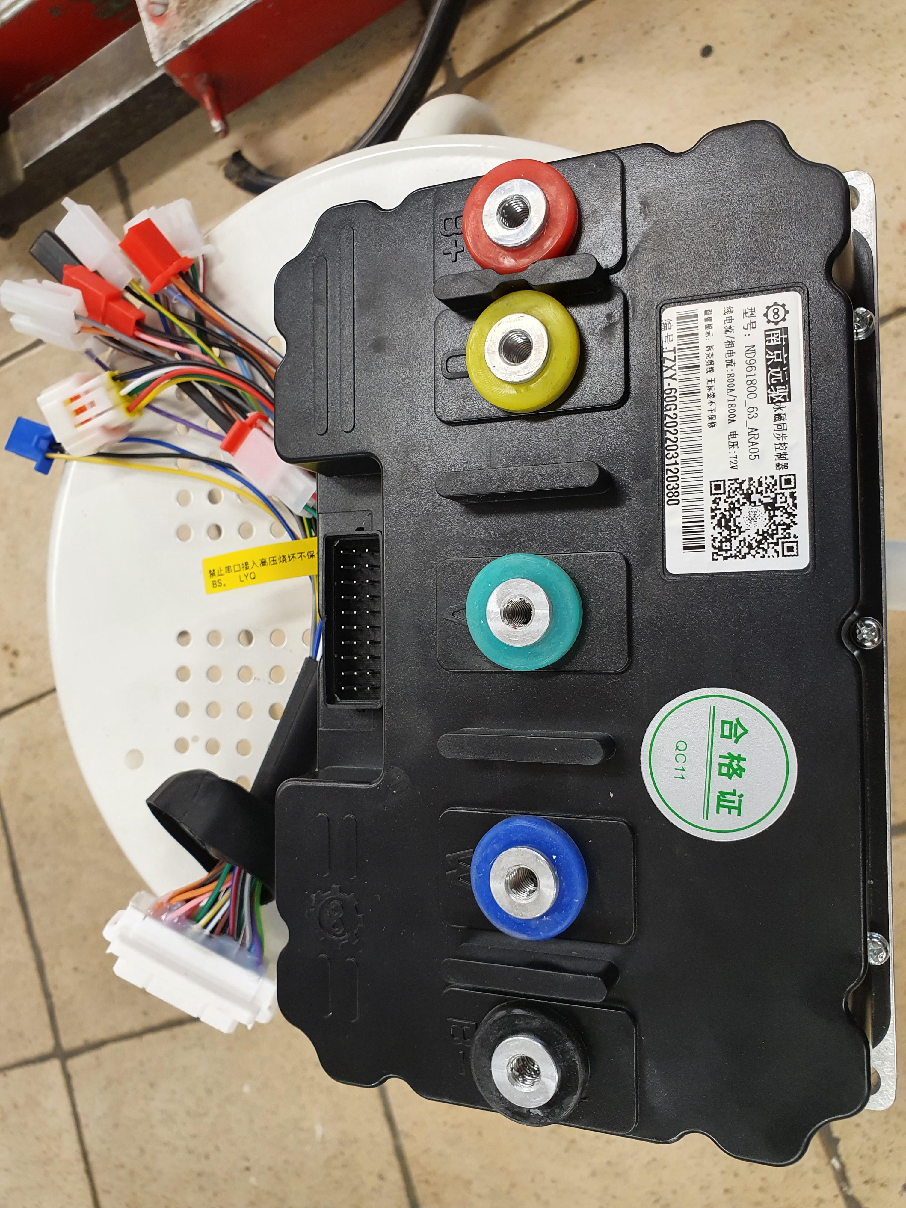
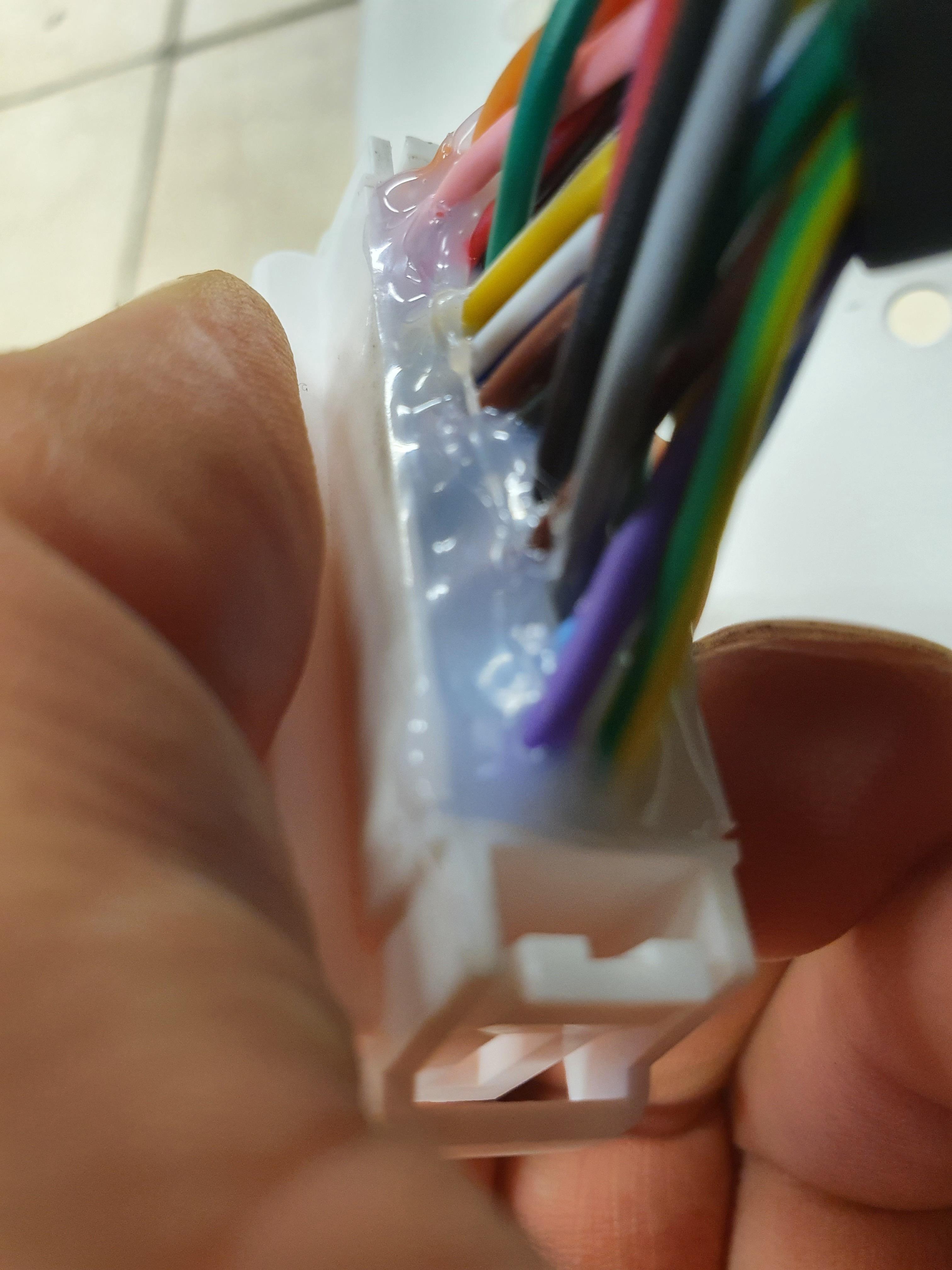
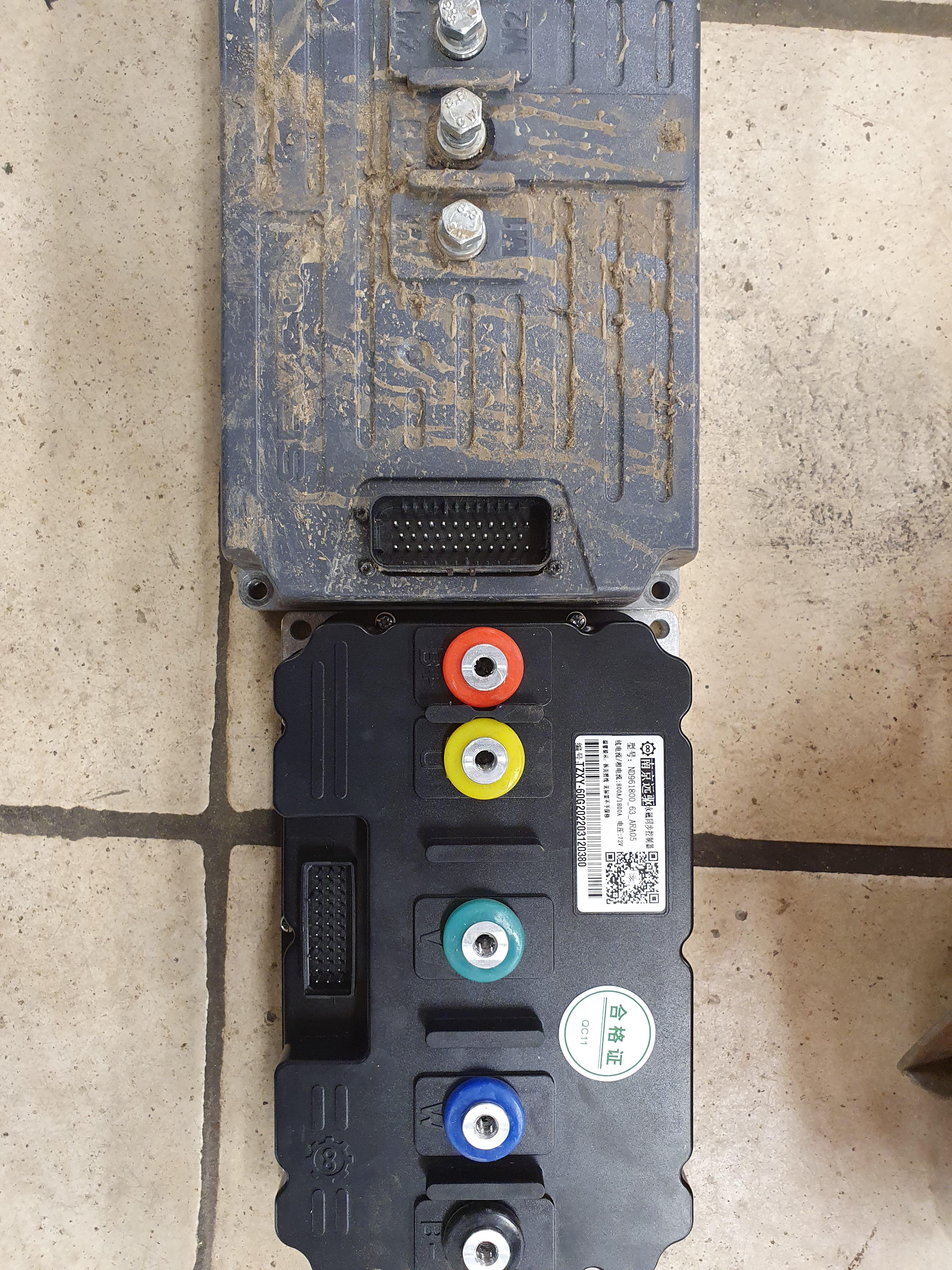
liveforphysics said:I would pack that connector with dielectric gel.
