ZombieSS's power stage for Lebowski's controller video pg17

not sure how much experience you have soldering SMT, but there are great videos techniques on youtube nowadays.

for TD350 and other SMD pins, really check close to see for solder bridge between legs. you should really use a magnifying glass for this. also, too much heat can ruin a chip so don't keep it on too long... hot but fast.
 
As a soldering instructor on my school, most students don't use enough heat - resulting in cold solder junctions. Some of these can look very normal indeed, but a thin film of flux is still present - due to inadequate heat. If you use lead solder and a 320 deg iron, you really need to be reckless to destroy most components.
 
I am getting nice molten puddles on one side then sliding the component into place and letting it cool. Then solder the other side. Working really well so far. I use a grounded tip 15w iron with a very tiny point. This is faster than through hole components. I think I am going to use more smd parts. I just need to invest in a high quality iron which I sadly have not done yet.
 
ya, and let us know how your new scope is doing.

ps. nothing hand solders surface mount chiclets like soldering tweezers. heats both sides simultaneously and allows you to put them on flat
 
Nice detail on how you equalized the resistive path among the paralleled MOSFETs. Not exactly symmetrical, but a good compromise I guess. <strike>Similar on the +Battery.</strike> (damn strike!)

update: actually not on the +Battery, if I see it correctly... any comments?

update 2: I'm not being able to identify the return for the low side gate drivers... is this your final layout?

update 3: why is there "lonely" vertically placed 1uF cap on the right?
 

Attachments

  • zombiess-pwr-stage-detail.png
    zombiess-pwr-stage-detail.png
    12.4 KB · Views: 2,923
  • zombiess-pwr-stage-detail-+.png
    zombiess-pwr-stage-detail-+.png
    12.2 KB · Views: 2,921
I don't think the current path needs to be perfect, I don't think that's even possible, all one can do is try to get it in the ball park. You'll drive yourself mad trying to get everything perfect, sacrifices must be made and I thought this was the lesser of all the evils.

low side return is handled by jumpers over the phase on the underside, you might notice the landing pads I created where I left the solder mask off.

The cap on the right is a hobo, he tried to get personal counseling and even went to a motivational seminar hosted by Matt Foley. I asked that cap what he was doing there and he said "I'm 35 years old, eating a steady diet of government cheese, thrice divorced, and living in a van down by the river!"

That cap will not be populated and is an outcast. It was placed there as an option if I decided I needed it for some reason.
 
Did a few simulations, indeed the DC resistance on your layout geometry and IRFB4115 FETs is not relevant for power dissipation. But asymmetric layout is also asymmetric inductance; in a 1st approach did a few simulations that show a very relevant difference in current sharing among the 4 paths when switching, assuming just 5nH inductance difference from a path to next path, but I need to work more on this as I have some doubts about the simulation validity.
 
I am past simulation. I am building and testing. While there may be stray inductance to worry about, I believe the overlapping battery power plane will reduce the induced magnetic flux if I understand the theory correctly. Shouldn't the key to mitigating effects of stray inductance start by reducing how much is produced?
 
From what I've seen in my investigations the overlapping battery power plane will act as a bus bar and will
help, but ONLY if all 3 phases are closely build together. If you have 3 PCB's, one per motor phase,
and connect those together with wires, it's all out the window...

I have a strong feeling that if you want to build a 24 FET controller, it's best to build 4 very compact
6 FET output stages (with closely spaced bus bar, 2 rows of 3 FETs, the 2 FETs per motor phase opposite
each other, and each 6 FET having a 220uF and a narrow 470nF cap on the supply). Those 4 stages can
then be hooked up in parallel with wires, but make sure everything is star connected with equal wiring length.
 
replying to your private message here if you don't mind, so everyone can see & comment. Loop area in gate drive layout is very imporant because there are regions within the gate drive that have very high di/dt, i.e. rate of change of current.
big loop area + high di/dt (or dv/dt) = antenna = EMI radiation = corruptionn of signal = poor performance or failure = bad.

so you should take every opportunity to consider what the loop area is and to make reduction where ever possible.

note that a long trace with good reference running parallel directly below (on separate layer in PCB obviously) is better than short length with reference trace offset or on same layer but beside signal trace (increased loop area). if possible, reduce lengths too, but if forced to make a choice, chose minimization of loop area as priority.

i attached a couple pictures to given some idea of what i mean
 

Attachments

  • gateDrive_loopArea.jpg
    gateDrive_loopArea.jpg
    77.8 KB · Views: 2,596
exactly. twisted pairs is really common also for 6-pack modules when gate driver is not mounted on top. basically in line with idea that length of wire is not nearly as important as keeping loop area small, twisting flying leads does the same thing.
 
Progress update. I am finally working on building these driver boards again. I just finished up soldering all the SMD components to the board which is the bulk of the soldering. I wasn't able to do this until now because I lacked a crucial tool, a good soldering station. I happened to drop by Fry's electronics after work tonight to find a Molex connector I needed and while browsing the isles found a Hakko FX-888D on sale for $65. Figured I had nothing to lose at this price.

I have no idea why I waited so many years to get a soldering station, this makes soldering soooo much easier. I had done a really crappy job attaching 2 of the TD350E SO-14 packaged ICs and struggled all the way. A quick you tube video on SMD soldering and about 20 mins later all 6 of the drivers were soldered with beautiful connections and no bridges. Solder flux pen + the right tip and drag soldering FTMFW! These devices are so easy to solder now.

The next major hurdle will be building heat sinks for the FETs. I have a mini mill but have never used it. Need to take it out of the crate and clean off the cosmoline.

Most of my future projects will now be SMD since they are so easy to work with and use much less board space.

BTW, this setup has a target power of 125V max, 200A burst, 100A continuous. The continuous rating will really depend on how well the FETs are heat sinked and attached to a case which does not exist at this point. Putting all of this in a box is going to be a major challenge. Next version should be smaller.
 
you won't regret it.

you need also a very good pair of tweezers, 6" long min with sharp end and also another pair with blunted ends. a good magnifying glass to check for solder bridge and as zombiess says, good soldering iron with adjustable heat & high quality needle tip (this is important because low quality does not clean up well nor transfer heat well which is important when tip is so sharp). if you can spring for it, an overkill unnecessary soldering tweezer is good too because it heats both sides of a SMD resistor/capacitor simultaneously so easy to get the thing to sit very flat (looks professional). videos too have come a long way, wish they were around when i started!
 
I am using a cheap set of tweezers from Harbor freight. A whole set cost me about $3 but they work good so far. They are about 6" long and have needle and blunt tips. I am finding smd assembly takes about the same amount of time as through hole and is much cleaner since leads don't need to be trimmed. I have been resistant to go smd in the past due to the time and tools required, but everything has come down in cost. I am also finding PCB layout to be easier with smd parts. I am starting to wish I would have gone smd sooner. These driver boards are a mix of through hole and smd. The next version will be all smd where possible unless through hole makes more sense for a component.

On these boards I placed a few components on the rear of the PCB because of space and routing. I try to do this sparingly on gate drives and only with components not in the gate loop.

I purchased 4 additional tips for the station at the same time knowing I would be doing smd. The one tip is extremely small, small enough to place in between an so-14 packages legs and only heat a single leg. This is how I initially tack and apply solder to the chip and often end up with solder bridges which are fixed by lightly fluxing with a flux pen and drag soldering the legs with the long needle tip. End result looks like it was done in a reflow oven. For good measure I switch tips to a 3mm chisel and then heat each leg to ensure solid bonding. I probably don't need to do the last step, but it makes an even nicer finish and only takes about 0.5s per leg. I can touch the chip immediately after soldering and its only warm, so I know I am not cooking it. For these small ic packages I have son solder that is smaller than .032", not sure where I got it since its at least 10yrs old but it works good. The new 0.032" no clean solder is nice too. Once I am done I'll remove the flux and should have a nice finished board. I will try to post some pics of the finished smd work tonight.
 
Smd's are all nice and so on when you have a mature design, but when gate drivers start blowing up and you have to start replacing parts... dil's in sockets are very easy to replace. But i think a hakko like you got will be a good investment, especially for playing with ARM processors...
 
Next up is a hot air rework station. They are cheap and make removing smd very easy. I already purchased a $200 vacuum desoldering iron by Hakko and in it paid for itself in just 2 months. Its easier for me to justify these purchases since I have a business I am using them for.

Desoldering gun is amazingingly useful. I have managed to harvest good parts and fix previously broken stuff I had in a box.
 
OK everyone, I have finally made some HUGE progress. It's not running yet, but it's getting really close now. Virtually all components are installed on the board. I have yet to install the FETs and the gate drive resistors. I need to come up with a cabling system next so I can connect all this stuff together.

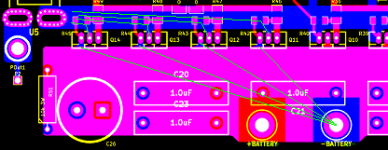
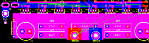
Here is a picture of what I have so far. I started building up the trace on the one board. It will have 2 parallel strands of 10 AWG. I need to order the aluminum bar stock for my heat sink, but I can't really do that until I can find a case that I know I'm going to be able to fit this beast in, that's going to be a challenge for sure. I am thinking this will live the majority of it's life as an open frame experiment and I'll use a redesigned one to power my bicycle. I'm pretty much committed to going SMD for all my future work. I just found some cheap 0805/1205 sized resistor and capacitor kits on ebay for a great price. I could have saved myself some money had I already had them on hand.

I really really hope that after all of this work, I am able to get this working... aka I didn't mess up my schematic and therefore my layout.
Lebowski Controller 1.jpg

This is one of the TD350E drivers I soldered. I haven't cleaned off the flux yet since I'm not done with the board, but this should give you an idea of how the chip looks. Sadly the SO-14 package is by far the cleanest solder joint on the entire board :( I started building before I had a good station. At least the most critical part looks pretty.

SMD SO-14 Package.jpg

I just purchased two isolated 24V 20A supplied from a forum member here so I can run a 48V, 20A setup (can peak to 40A) without having to use batteries while doing initial testing. I am a wee bit scared to setup some high power LiPo and use it inside on a beta setup, I've been known to make mistakes and would prefer not to lose a pack :oops: Not a lot to start off with, but it will certainly make me feel a bit safer. Maybe if I can get this working well I can work with Arlo1 and have him scope and test it on Colossus to see how it does under a real load.
 
Zomb... just don't want you to get discouraged. My experience has shown that it typically takes 3 "turns" (pcb versions, revised, etched and stuffed) to finally get a production ready prototype for new designs. That was the rule of thumb that I used for years in planning programs. It usually allowed us to have somewhat realistic cost and schedule estimates.

If you beat that with a new design, you should really toast your achievements! You will be in the upper tenth of one percent of designers. I am hoping that you are!
 
bigmoose said:
Zomb... just don't want you to get discouraged. My experience has shown that it typically takes 3 "turns" (pcb versions, revised, etched and stuffed) to finally get a production ready prototype for new designs. That was the rule of thumb that I used for years in planning programs. It usually allowed us to have somewhat realistic cost and schedule estimates.

If you beat that with a new design, you should really toast your achievements! You will be in the upper tenth of one percent of designers. I am hoping that you are!

If this succeeds to my goal of 200A max, then it's a credit to the people who have held my hand and helped educate me. Even if it fails it's still an insanely educational project. It took months of design revisions / review by someone who has been there and made things work before these PCBs were ever sent off to be fabbed. There are probably over 100 design revisions. I had to be educated on even the simplest things such a creepage, clearance, decent ground plane rules, the list goes on and on. This is by far the single most complex project I have ever attempted, especially since I am not very good at analog design, but am improving.
 
When I'm soldering SMD components, which is the type I prefer, I apply a little solder to one of the pads, place the component, heat the solder and press the component down to the PCB. Now the component is fixed in the correct location, and I solder the other pads, starting in the opposite corner when doing IC's. The very first solder joint that fastened the component is reheated and applied the correct amount of solder.

When hand soldering SMD's, it's a good idea to make the PCB pads a bit larger than what is needed for reflow soldering, or at least the pad is a bit bigger than the SMD leg, so you have a bit of pad area to apply heat to when soldering.

A thing I have been wondering about, is whether the manually applied solder, when soldering SMD's by hand, gets in between the SMD leg and the PCB pad, or the solder just wraps around on the outside of the leg, creating an inferior connection.
 
Back
Top