
You are using an out of date browser. It may not display this or other websites correctly.
You should upgrade or use an alternative browser.
You should upgrade or use an alternative browser.
ZombieSS's power stage for Lebowski's controller video pg17
- Thread starter zombiess
- Start date
zombiess
10 MW
bronz said:Why did you decide to design and build a controller zombie? Was it for the fun of it or does this new controller afford you better performance or something? Just curious.
One of my hobbies is learning. I did not design the controller, I designed the driver and power stage with HighHopes guiding me.
Designing a good gate driver layout is like trying to solve a difficult 3d puzzle.
HighHopes
10 kW
- Joined
- Mar 28, 2013
- Messages
- 929
that's an interesting way to phrase it, ha!Designing a good gate driver layout is like trying to solve a difficult 3d puzzle.
zombiess
10 MW
Let the games begin...
I managed to get one of the power stages up and running for testing tonight. No double pulse test or load testing, but I verified the circuit switches. I setup a PIC to output a 19khz waveform and then scoped the gate - source. I am starting off with 40ohm on and 30 ohm off gate resistance since I have just one IRFB4115 installed. Switches 0 to 7V (miller plateau is around 4.8V) in 260nS. I bypassed the gate resistors and saw the switch time drop to about 83nS (0-17V, it overshoots a bit) which matches up pretty will with the data sheet rise time of 73nS.
I watched the 2 step turn off function, it reduces the gate voltage by about 1.5 volts for ~1.7uS
Miller clamp is engaging right around 1.8V
One thing that really has me concerned is the propagation delay. So far it's at 2.1uS from the output of the opto switching low to the gate drive starting to switch high. This is much longer than the data sheet max of 800nS. Not sure what's going on here. I am unsure of the propagation delay from the input signal of the opto to the output which has to be added to the already long 2.1uS.
Lebowski
10 MW
is there a schematic somewhere ?
zombiess
10 MW
Lebowski said:is there a schematic somewhere ?
Very first post of this thread. It's a zip, files are in kicad format, I included the needed libraries with my custom components. Board layout is in there too.
Just to confirm with D-S one should see zero gate ring no matter how fast you switch, correct? Ringing should only become an issue under load?
I am wondering if my propagation delay is the miller clamp, I have to re read the app note and possibly bypass it for verification.
Just for fun I added the other 3 MOSFETs for a total of 4 and with a zero ohm gate resistor it switched them in around 110nS 0-17v. Slamming the gate like an angry kid slamming his door.
Lebowski
10 MW
HAVE A LOOK AT THE CURRENT SENSORS, IN THE SCHEMATIC THEY'RE THE WRONG WAY AROUND !!!! OUTPUT STAGE MUST BE ON PIN 4, MOTOR ON PIN 5
zombiess
10 MW
Lebowski said:HAVE A LOOK AT THE CURRENT SENSORS, IN THE SCHEMATIC THEY'RE THE WRONG WAY AROUND !!!! OUTPUT STAGE MUST BE ON PIN 4, MOTOR ON PIN 5
Which board? Need more detail. I have not tried running anything other than the driver so there is plenty of time to correct a board error.
OK, I just saw what you mean on the current sensor, that's a easy fix, I'll just flip the current sensor to the bottom of the board and pin 4/5 are then in the correct position, problem solved. My output from the sensor is on 3 pins and my header is directly connected to them. I made non populated holes for noise reduction so I can move the decoupling cap over.
Thank you for pointing this out Lebowski, this will save me many hours of trouble shooting. I guess when I drew this I did not understand the schematic for the current sensor correctly, at least the fix is easy. (Honestly I knew I'd probably have to make a change or 2 to my boards and sorta planned ahead with a few points to tie into.
I just noticed that I had the voltage input wrong with the voltage for Phase B going to 7 instead of 8 on the brain board, that's an easy fix too since I am using a screw block to connect those. Out of all the times I looked at this circuit I just noticed that was wrong compared to your schematic, whoops.
zombiess
10 MW
Ok, I just checked the TD350E app notes and saw that my propagation delay is being caused by the 2 level turn off. It delays the turn on by the same amount as the turn off, 1.8uS in my case. Since I'm seeing about a 2.1uS delay and my 2 level turn off is 1.8uS that means my propagation delay without the 2 level is going to be ~300nS + what ever the opto is. This is in line with the TD350 spec sheet  .
.
I am unsure how much the 2 level turn off helps with a MOSFET when a over current shut down is experienced. The app notes are mainly directed at IGBTs and reducing the big Vce spike that occurs, I'm not familiar enough with FETs to know if this same spike occurs at Vds. If it is of benefit to MOSFETs I can always tweak the time and level by adjusting the components. *edit& Just read a IXYS datasheet on the IXDD414 where it talks about using a very similar feature to reduce the chance of failure on MOSFETs from over current and avalanche breakdown from di/dt induced over-voltage transients.
Lebowski, will having this length, ~2.1uS, of propagation delay effect your controller at all? I am only planning to switch between 6-15khz, maybe 21khz if I want to try a really low inductance motor.
Just making these simple measurements and seeing things lining up with what was planned is getting me excited. I still need to do the double pulse tests to verify over current detection by the desat circuit and what ever other information it can give me.
I'm also trying to learn my new Rigol DS2072 scope. This scope has more options that I know how to really use. I'm only using the most basic features right now, but I just started using it last night, I'm already in love with it. The interface is intuitive and has oodles of configurable displays / data that can accompany the wave form. It makes my 10 year old Fluke 123 Scopemeter looks like a toy (a very nice and useful toy).
.I am unsure how much the 2 level turn off helps with a MOSFET when a over current shut down is experienced. The app notes are mainly directed at IGBTs and reducing the big Vce spike that occurs, I'm not familiar enough with FETs to know if this same spike occurs at Vds. If it is of benefit to MOSFETs I can always tweak the time and level by adjusting the components. *edit& Just read a IXYS datasheet on the IXDD414 where it talks about using a very similar feature to reduce the chance of failure on MOSFETs from over current and avalanche breakdown from di/dt induced over-voltage transients.
Lebowski, will having this length, ~2.1uS, of propagation delay effect your controller at all? I am only planning to switch between 6-15khz, maybe 21khz if I want to try a really low inductance motor.
Just making these simple measurements and seeing things lining up with what was planned is getting me excited. I still need to do the double pulse tests to verify over current detection by the desat circuit and what ever other information it can give me.
I'm also trying to learn my new Rigol DS2072 scope. This scope has more options that I know how to really use. I'm only using the most basic features right now, but I just started using it last night, I'm already in love with it. The interface is intuitive and has oodles of configurable displays / data that can accompany the wave form. It makes my 10 year old Fluke 123 Scopemeter looks like a toy (a very nice and useful toy).
HighHopes
10 kW
- Joined
- Mar 28, 2013
- Messages
- 929
terminal 4/5, bugger.. its definitely backwards. the sensor is bi-directional though, so the sensor won't matter which direction is which.. but the controller might care a lot. assuming for a moment that putting the sensor on the other side of the board (or reverse the direction current flows by cut & jumper) is noet possibl.. alternate solution: is it possible to multiply the measured current signal by -1 in software to make the correction?
2us delay is pretty long time for the 2-level shut off. probably means you have to play with the RC time constant (see app note page 10, equation 1). since the 2-level turn-OFF is there to protect against big voltage spike which occurs when mosfet turns OFF, then the timing of this should be a little bit more than the time it takes the mosfet to turn OFF. so, as measured drain-source, if you have 200ns switching (which is fairly fast) then 2-level turn-OFF time should be set to 250 to 300ns. probably in the end of your tuning you will decide to switch around 500ns, so 2-level turn-OFF time should be around 600ns.
the 2-level turn-OFF voltage, set by zener diode D12 in your schematic, is a voltage selected (zener diode part number) such that the mosfet goes into linear conduction range. the app-note shows 11V but that is for an IGbT which has much higher saturation voltage than a mosfet. at 11V on a mosfet you will not be in linear region, probably you will need 8 or 9 V zener diode. check your datasheet, or post & ask question if you're not sure what i'm talking about. it is definately still apply to mosfet as equal to igbt, just the voltage level is probably different. it is really useful for you i think.
i'm jealous of your scope
Zombies the current sensor will only work one way.... You might need to cut the traces the do it the right way. What sensor is it? Is it the Honeywell we got from big moose? If current goes though the ferrite core one way the voltage increases and if current goes the other way it will make the voltage output decrease.
A guy with your training should have no problem affording itHighHopes said:i'm jealous of your scope
zombiess
10 MW
Arlo1 said:Zombies the current sensor will only work one way.... You might need to cut the traces the do it the right way. What sensor is it? Is it the Honeywell we got from big moose? If current goes though the ferrite core one way the voltage increases and if current goes the other way it will make the voltage output decrease.
Allegro ACS758 200A inline sensor.
I don't see any need to cut traces or get crazy, the way my board is laid out the right way to fix it is desolder, flip it to the bottom side, solder it in, move the decoupling cap and re-pin the 3 pin connector that goes to the brain board. I can probably do all 3 boards in 1 hour. It seems like a minor fix to me, but I'm glad someone caught it because I totally missed it and wouldn't have found it until I tried to use the brain board.
I have 2 of the Honeywell sensors from Bigmoose and I also have 3 LEM HASS 600A sensors I picked up for another project that I can also utilize if I need/want to. I also have 10 more ACS sensors (bulk was cheaper and I plan to use them eventually).
Power consumption on the gate drives is pretty low so far 16mA each, no switching. Each isolated supply draws 23mA when the driver is under 50% dc @ 19khz PWM, each 1W supply has a maximum load draw of 50mA @ 24V input with a maximum output of 67mA @ 15V. Looks like I am using less than half of the 1W supplies capacity.
Arlo1, if you are interested in going to isolated supplies on your next design, I found a supplier in China that sells the same kind of 1W 24v-15V unregulated supplies for about $3 each, I was thinking of ordering some for future projects. Even if I only use 2 isolated supplies for an entire controller it's superior to boot strapping and makes the layout easier. Found some 2W units for $7 each, these would be good if I only want to use 2 supplies for high / low of an entire controller vs the 6 I am using now.
Yup lets have the link.zombiess said:Arlo1, if you are interested in going to isolated supplies on your next design, I found a supplier in China that sells the same kind of 1W 24v-15V unregulated supplies for about $3 each, I was thinking of ordering some for future projects. Even if I only use 2 isolated supplies for an entire controller it's superior to boot strapping and makes the layout easier. Found some 2W units for $7 each, these would be good if I only want to use 2 supplies for high / low of an entire controller vs the 6 I am using now.
I found 3 of mine that are not blown from my early days
Im going to test a bit with them soon. But I need more.
How many watt do you guys think I need?? I am using 4 4568 fets in parallel at the moment which have 151nc total gate charge per fet. And the ixfk230n20t will be 4 in parallel as well with 378nc total gate charge per fet (though it was more) but I thought I worked the math and the 1 watt isolated supplies were not enough for a set of 4 what do you guys think?
But yes Jeremy lets see the link.
liveforphysics
100 TW
$12 for an isolated 5w. Come in various voltages and a few higher and lower power levels. All pretty cheap with decent specs.
http://www.futureelectronics.com/en/technologies/electromechanical/power-supplies/ac-dc/Pages/7039474-PBK-5-24.aspx?IM=0
http://www.futureelectronics.com/en/technologies/electromechanical/power-supplies/ac-dc/Pages/7039474-PBK-5-24.aspx?IM=0
zombiess
10 MW
liveforphysics said:$12 for an isolated 5w. Come in various voltages and a few higher and lower power levels. All pretty cheap with decent specs.
http://www.futureelectronics.com/en/technologies/electromechanical/power-supplies/ac-dc/Pages/7039474-PBK-5-24.aspx?IM=0
wrong type LFP, we are talking DC-DC converting 24VDC to 15VDC for the gate drive with an isolated unregulated converter. My setup is designed to run off of 24V which will be regulated from what ever battery voltage I end up running.
Lebowski
10 MW
zombiess said:Lebowski, will having this length, ~2.1uS, of propagation delay effect your controller at all? I am only planning to switch between 6-15khz, maybe 21khz if I want to try a really low inductance motor.
I would say you would hear 6-15kHz PWM and that it would be annoying. I'd say you want the PWM outside of the audio band.
As long as it is delay and not deadtime, 2.1usec delay is no biggie.
So you tell us you have something but you don't let us see it or the link to order it???zombiess said:liveforphysics said:$12 for an isolated 5w. Come in various voltages and a few higher and lower power levels. All pretty cheap with decent specs.
http://www.futureelectronics.com/en/technologies/electromechanical/power-supplies/ac-dc/Pages/7039474-PBK-5-24.aspx?IM=0
wrong type LFP, we are talking DC-DC converting 24VDC to 15VDC for the gate drive with an isolated unregulated converter. My setup is designed to run off of 24V which will be regulated from what ever battery voltage I end up running.
zombiess
10 MW
Arlo1 said:So you tell us you have something but you don't let us see it or the link to order it???zombiess said:liveforphysics said:$12 for an isolated 5w. Come in various voltages and a few higher and lower power levels. All pretty cheap with decent specs.
http://www.futureelectronics.com/en/technologies/electromechanical/power-supplies/ac-dc/Pages/7039474-PBK-5-24.aspx?IM=0
wrong type LFP, we are talking DC-DC converting 24VDC to 15VDC for the gate drive with an isolated unregulated converter. My setup is designed to run off of 24V which will be regulated from what ever battery voltage I end up running.
http://www.aliexpress.com/wholesale?SearchText=24v+isolated+15v&catId=0&initiative_id=AS_20140122120859
The ones I have now are Mornsun brand and had spec sheets. The first link on that site has B2415LS-1W "ND" brand same part number for $2.60 USD each. You can usually get detailed data by emailing the seller or doing your own homework. Personally, I'm willing to gamble $26 and load test them myself. I already found my 1W rated Mornsun brand converters can do over 1W with no noticeable issues, it needs further testing.
Ali Express is my Kryptonite for some electronics parts. You must use some caution and common sense though, such as don't buy IRFB4110 FETs.
Alieexpress also has several sellers offering HUGE SMD kits of resistors and caps, different tolerances ratings, some already organized in books for a killer price. I will be ordering some as it will save me a lot of money on my next few projects to have this stuff in stock vs sucking it up paying Digikey for the small orders of 10-50 pieces as I have done recently.
*edit* I found the store of the "manufacturer" and they have the spec sheets posted, Nengda Power Technologies
http://www.aliexpress.com/store/321802
HighHopes
10 kW
- Joined
- Mar 28, 2013
- Messages
- 929
Allegro ACS758 200A inline sensor.
zombies, be careful about the sensor. read the datasheet to get the exact part number, you need the version that is Bi-directional as your phase current alternates between positive & negative values.
with Bi-directional sensor, then, maximum positive (peak) current is given as 5V at output of sensor, 0 Amps is given as 2.5V and minimum negative (valley) current is given as 0V. hopefully your brain board is expecting something like that and/or you have adequate signal conditioning path that can make the translation (as well as filtering as required).
zombiess
10 MW
HighHopes said:Allegro ACS758 200A inline sensor.
zombies, be careful about the sensor. read the datasheet to get the exact part number, you need the version that is Bi-directional as your phase current alternates between positive & negative values.
with Bi-directional sensor, then, maximum positive (peak) current is given as 5V at output of sensor, 0 Amps is given as 2.5V and minimum negative (valley) current is given as 0V. hopefully your brain board is expecting something like that and/or you have adequate signal conditioning path that can make the translation (as well as filtering as required).
All the sensors I have are the bidirectional version, I made sure of that when I ordered because I intended to use them on Lebowskis controller and or other projects.
Now I need to find a spool of wire so I have an inductor to play with, they are in a box somewhere in my office, I still haven't organized very well since moving last month. I have an LC meter so I'll be able to measure it and make the calculations. For desaturation testing you mentioned lifting the diode to force it to engage, but can I not test it by just using the inductor and forcing a short high current pulse? I think this is what you suggested in your detailed post.
HighHopes
10 kW
- Joined
- Mar 28, 2013
- Messages
- 929
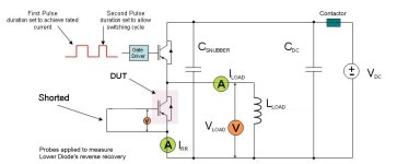
yes you can jump direct to the double pulse method. keep in mind you do not yet know if the protection scheme will work.. so build up slowly your applied voltage switching minimal current.. then when you are at rated voltage (your application voltage, not your mosfet max voltage rating), then start ramping up the current. so, start with a short pulse of 5us or so. double pulse then would be 5us, off for 5us, on for 5us. see what peak current you reach (but you will have an idea because you pre-calculated so know what to expect). you want some small current.. if you have just ONE mosfet then you want something like 5 amps for that very first pulse. then increase the pulse ON time slowly, creaping up to the level of current that you want to detect a desat failure. so for just ONE mosfet, then what current would that be? if package is 75A limited, but you know not to use it beyond 35A (this is a number you said to me in the past) then the de-sat trigger current should be somewhere around 50A. so if you are slowly increasing your double pulse ON time and are measuring above 50A.. 60A... 75A... and still no fault trigger, time to stop and figure out what is wrong.
for the double pulse, the first pulse is generally twice as long duration as the second pulse. so the first pulse builds up the current, then OFF for short time (about half the time of your second pulse) and then second pulse duration is ON for half the time of the first pulse and you expect to reach a fault trigger during this second pulse. by the end of the test, when you are nearing 50A and expect to see a de-sat fault trigger, the first pulse should be approximately 1/fsw, off for 0.5 * 1/fsw and second pulse ON for 0.5 * 1/fsw. these are just rough numbers, pretty flexible. fsw = your switching frequency, typically 20kHz (outside audible range as lewbowski mentioned). technically we would use 18khz or 21kHz because that is evenly divided by 3 which is good for harmonic reasons but for historic reasons based on your ear hearing range, industry adopted "20kHz" as the standard value.
for the double pulse, the first pulse is generally twice as long duration as the second pulse. so the first pulse builds up the current, then OFF for short time (about half the time of your second pulse) and then second pulse duration is ON for half the time of the first pulse and you expect to reach a fault trigger during this second pulse. by the end of the test, when you are nearing 50A and expect to see a de-sat fault trigger, the first pulse should be approximately 1/fsw, off for 0.5 * 1/fsw and second pulse ON for 0.5 * 1/fsw. these are just rough numbers, pretty flexible. fsw = your switching frequency, typically 20kHz (outside audible range as lewbowski mentioned). technically we would use 18khz or 21kHz because that is evenly divided by 3 which is good for harmonic reasons but for historic reasons based on your ear hearing range, industry adopted "20kHz" as the standard value.
zombiess
10 MW
For the desat test I will probably start out lower by reacalculating the zener value for a much lower amp trigger point before going to a full scale test. Pretty simple to do, swap a zener and test at lower current for less risk, then step up.
zombiess
10 MW
OK, I need an explanation, why does this test work for testing desaturation?
I have my spool of wire and it is 509uH, so according to the math provided above and 25V on the DC bus I get 100A (I'm just using 500uH for the inductor value, pretty handy the first spool of wire I grabbed happened to measure right at 500uH, huh?).
Desaturation detection kicks in at 7.2V detected on the pin (I'm still not 100% on how this actually works). Anyways I have my 5.1v zener in front to help lower the detection voltage since FETs have much lower RDSon values, read about the zener trick in an app note somewhere and now I don't remember where.
The desat calculations Desat Pin Voltage = 1.2v +Id * Rds_On
Normal operating conditions and over current conditions Peak Over Current = operating RMS * 1.41 * 1.25 (over current trips at 125%)
My maximum normal operating parameters is 50A RMS per FET with peak over current triggering the desat protection at 88.1A
From 0C to 125C this puts my Desat voltage at a min of 6.92V at 0C and 8.15V @ 125C when I = 88A peak
The reason for choosing the desat point above is compensate thermally for the Tjc of the FETs is 125C (which means higher RDSon) the desat protection kicks in at just 25A RMS or 44A peak per FET. Kind of a built in derating as temps go up.
I fully admit I'm weak on the match when it comes to working with inductors, I need some tutoring. I feel dumb again but I want to make sure this stuff works correctly before going balls out and trying to drive a motor.
measure your spool of wire for inductance value (you have this feature in handheld meter correct?). calculate approximate ballpark you need by I = L*dv/dt. I = current needed to trigger your desat under normal use (200A?, i forget what we designed it for). L = your spool of wire. dV = allowable voltage drop of DC Link cap during this test = 20%, or 0.2 * test voltage = 0.2 * 50V = 10V. dt = lenght of time of individual pulse (use 50% of your target switching frequency, so for 20kHz switching then 25uS is time to use in your calculation).
I have my spool of wire and it is 509uH, so according to the math provided above and 25V on the DC bus I get 100A (I'm just using 500uH for the inductor value, pretty handy the first spool of wire I grabbed happened to measure right at 500uH, huh?).
Desaturation detection kicks in at 7.2V detected on the pin (I'm still not 100% on how this actually works). Anyways I have my 5.1v zener in front to help lower the detection voltage since FETs have much lower RDSon values, read about the zener trick in an app note somewhere and now I don't remember where.
The desat calculations Desat Pin Voltage = 1.2v +Id * Rds_On
Normal operating conditions and over current conditions Peak Over Current = operating RMS * 1.41 * 1.25 (over current trips at 125%)
My maximum normal operating parameters is 50A RMS per FET with peak over current triggering the desat protection at 88.1A
From 0C to 125C this puts my Desat voltage at a min of 6.92V at 0C and 8.15V @ 125C when I = 88A peak
The reason for choosing the desat point above is compensate thermally for the Tjc of the FETs is 125C (which means higher RDSon) the desat protection kicks in at just 25A RMS or 44A peak per FET. Kind of a built in derating as temps go up.
I fully admit I'm weak on the match when it comes to working with inductors, I need some tutoring. I feel dumb again but I want to make sure this stuff works correctly before going balls out and trying to drive a motor.
Similar threads
- Replies
- 24
- Views
- 2,047
- Replies
- 182
- Views
- 19,570
- Replies
- 23
- Views
- 6,175
-
- Locked
- Replies
- 120
- Views
- 20,711