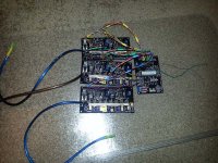
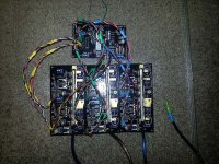
ZombieSS's power stage for Lebowski's controller video pg17

Futterama said:
When I'm soldering SMD components, which is the type I prefer, I apply a little solder to one of the pads, place the component, heat the solder and press the component down to the PCB. Now the component is fixed in the correct location, and I solder the other pads, starting in the opposite corner when doing IC's. The very first solder joint that fastened the component is reheated and applied the correct amount of solder.

When hand soldering SMD's, it's a good idea to make the PCB pads a bit larger than what is needed for reflow soldering, or at least the pad is a bit bigger than the SMD leg, so you have a bit of pad area to apply heat to when soldering.

A thing I have been wondering about, is whether the manually applied solder, when soldering SMD's by hand, gets in between the SMD leg and the PCB pad, or the solder just wraps around on the outside of the leg, creating an inferior connection.
This is how I do it as well. I think if you get the temp right it will flow into all the places it can the same way it would using an oven. I find this technique to work very well.

I just got a set of tweezers and the biggest thing that helps is getting a pad soldered and ready.
You should also go over all pads with a flux pen.
 
More progress. Eight gauge phase wires added, B+, B- and Phase out traces are built up each with two side by side strands of 10 gauge copper wire to make sure they handle the current. It was a little tricky to keep the board from warping a lot, but I managed.

All that is left now is installing the caps, FETs, gate resistors and the jumper wires needed to connect to the brain board. Biggest problem with the FETs is going to be the heat sinking since I'm not good at machining. Honestly that's probably going to be the single point that holds me back. I have some really small heat sinks I can install for unloaded motor testing.

I still have no idea how I will manage to put any of this into an enclosure of some sort. The design just doesn't lend itself to it very well and I don't have a load cell to test with. Probably shouldn't worry about that now since I still need to power it up and verify it works, one step at a time.
 
I still have no idea how I will manage to put any of this into an enclosure of some sort.
large tupperware tubs are on sale at walmart right now. sorry, i don't have any mechanical skill and my carpentry is even worse.
 
HighHopes said:
I still have no idea how I will manage to put any of this into an enclosure of some sort.
large tupperware tubs are on sale at walmart right now. sorry, i don't have any mechanical skill and my carpentry is even worse.

I am literally :lol: at that... Because when I was younger and had even less skill I have used Tupperware to house a project.

I need to get my mini mill setup and start learning. I have wanted a drill press for a long time (mainly for making holes in enclosures and other light duty work) so when I figured out a 25% coupon Harbor freight I had worked for online purchases I went for the gold and ordered a table top mill. Ended up costing me about $450 delivered. I don't know how to use a mill, but I figure between YouTube and Google I'll eventually figure it out... When I decide to start.
 
More progress. I am now at the point of adding FETs (will start as a 6 FET), Caps and at least putting current limited power to it and doing the first smoke test. If all goes well I might be able to test it on a motor this weekend, assuming I don't have any PCB errors which require fixing fist.

Built all of the jumper wires which always takes me much longer than I think it will. Not a fun process, but at least it's done. Three pin wires from the current sensor are braided, I don't think this will interfere with the signal at all, it receives power from the brain board and sends the signal back.

The 4 pin headers for high/low side contain two pairs of signal wires. The PWM/Gnd reference from the brain board which I twisted together, then the +5v from the brain board to power the opto which signals a fault back, both of these wires are twisted and then twisted again with the PWM signal. I don't think the twisting the two separate pairs together for neatness will cause any issues, comments welcome. I'm trying to keep the wiring somewhat neat so that I can easily identify what goes to what and avoid mistakes. I color coded each bundle with heat shrink tubing, I will mark the high side with a stripe from a sharpie to hopefully avoid mixing the high/low PWM signals.

I am nervous for the first power up (which will be done slow and with a current limit). This is by far the single most complex circuit I have ever designed/built. Once I know my Lebowski brain board works, I will draw up a new board layout using mostly SMD components to miniaturize it. I also have a new 12 FET TO-247 layout just about ready to send off to OSHpark which fits into an enclosure I have and will fit on any of my bikes. It's lacks the bipolar boost stage and desaturation detection, but is still opto-isolated using a gate driver which has an integrated miller clamp.

Feels good to be making progress vs having blank PCBs and a box with +$200 in components (I purchased enough to build more than one) just sitting around.

lebowski1.jpg

lebowski2.jpg
 
I build and test by modules, usually going from input to output. Have a power supply on the board? Build it and test it 1st. On success, then build the next part and test, and so on. Sometimes it can make sense to test an output part first. It's easy to see that, if you screw with the power supply, your next stage can be toasted, if you screw with your brain building, your power stage can be toasted, and so on.
 
NJay - i do the same.

also it is important to test the protection features before real power. gate drive under voltage, de-sat shoot-through, etc.

Zombiess, keep in mind that the power supply you have with current limit.. lets say you dial down the current limit to somethings super safe like 1amp, for arguments sake. then, you dial up the voltage testing at every 25V incrememt with 20 minutes duration at each stage watching.. all goes well, so you get all the way up your bus voltage, maybe 100V or whatever. then, lets say at that point for some reason a shoot-through happens and for some reason you did not validate desat circuit first and/or for some reason it fails to work properly.. so your power supply current limit might save you? maybe not.. the power supply has internal a large capacitor to minimize voltage ripple and that energy stored in the cap is not limited by the built in converter power supply current limit. it might, depending on the size of your DC/DC supply, be enough to vapourize your mosfets when it gets suddenly depleted. when i had very big supply for testing (it was size of a coffee table) i put a resistor (size of my hand) in series with the cable and put a fan on it during test.

anway, take your time. learn the limitations as you go along, stay safe.
 
Yup take your time and test everything you can imagine.
 
zombiess said:
The PWM/Gnd reference from the brain board which I twisted together, then the +5v from the brain board to power the opto which signals a fault back, both of these wires are twisted and then twisted again with the PWM signal. I don't think the twisting the two separate pairs together for neatness will cause any issues, comments welcome.
I would scope it to make sure it doesn't have the PWM "crosstalking" into the 5V in any relevant level.
 
what do you mean by PWM crosstalk to 5V? i'm asking because quality & cleanliness of PWM signal is vitally important.

it is not unusual to see logic gates ensure complimentary signal (outside of controller) followed by differentially driven to gate driver opto-coupler input at rather high mA level. then gate drive IC has function to ignore any "glitch" or all signals must be at least 100ns long before it is recognized. that's fairly robust signal routing.. but its important because any errant PWM signal has potential to do harm .. so it is strictly controlled.
 
Njay said:
zombiess said:
The PWM/Gnd reference from the brain board which I twisted together, then the +5v from the brain board to power the opto which signals a fault back, both of these wires are twisted and then twisted again with the PWM signal. I don't think the twisting the two separate pairs together for neatness will cause any issues, comments welcome.
I would scope it to make sure it doesn't have the PWM "crosstalking" into the 5V in any relevant level.

What is the likelihood of crosstalk if the pwm is the same +5v source. There are no high current transients. I have done this bundling before with pwm and not had issues but I am not an expert.
 
I was just thinking of capacitive coupling of the PWM signal (since this is the only one changing) into the 5V signal due to them going near, not saying there is a problem, just saying it doesn't hurt to check. I don't know if it's a relevant effect with these lengths, but these microcontrollers "today" have quite fast raise and fall times (this is not let's say, I2C, which is "slew rate" limited). 5V is fixed but it is to power the opto according to your description.
 
desat testing is a 3 part proceedure.

1, test that the desat signal can work, a fault signal is issued, all PWM shuts down. battery pack is not connected to inverter, the desat signal is "faked" by lifting the diode so it triggers for sure. monitor that fault signal is issued, confirm ALL 6 PWM channels shut down. get a sense of how long this process takes.

2. put in single mosfet and build your confidence that you can switch relatively low voltage. by the way, never ask mosfet to switch a DC bus less than 25V in your application. so, say 50V to leave room for droop without causing problem, you run the actual de-sat test. like so:

i. wire up the system. contactor between battery & inverter (read later to discover why). add an inductive load between phase A and ground. solder a shorting wire between gate/source of all mosfets except for Phase A upper (the gate drive under test). the phase A mosfet has to be installed though as you do need its diode. you don't want any other mosfet to turn ON by accident under due to noise like miller effect or something so this is why it is directly soldered (best active clamp you can get!). the inductive load can be a spool of wire, gauge is not important as test is for 10's of microseconds. air core is important though, don't want to saturate your inductor (spool of wire). put a probe on your current sensor so you can get an idea of waht the pulse current is through your inductor.

measure your spool of wire for inductance value (you have this feature in handheld meter correct?). calculate approximate ballpark you need by I = L*dv/dt. I = current needed to trigger your desat under normal use (200A?, i forget what we designed it for). L = your spool of wire. dV = allowable voltage drop of DC Link cap during this test = 20%, or 0.2 * test voltage = 0.2 * 50V = 10V. dt = lenght of time of individual pulse (use 50% of your target switching frequency, so for 20kHz switching then 25uS is time to use in your calculation).

here is the important part. somehow you have to generate only ONE pulse. well, ideally, two pulses for "double pulse" test which you can google to learn more now that you have the buzz word, but probably it will be easier to generate just one pulse for this de-sat test one pulse is OK. maybe it is with a waveform generator tired directly to your phase A upper gate drive input side? maybe it is a 555 timer circuit.. maybe you ask lewbowski make some test code? maybe you have not possible to make just one pulse so you have infinit amount then probably you can just stop here as the test will become too unsafe to continue... or maybe you risk it since somehow you must test the desat circuit. anyway..

ii. charge DC link capacitor to test voltage, say 50V.

iii. remove battery pack (don't want to damage anything and also want to make sure only small amount of energy is in the system). for removal of battery pack while DC link is energized a safe way to do this is with a contactor. probably you do not want your DC Link bleed resistors populated during this test.

iv. start with 10uS pulse duration. issue single pulse and watch current rise in your load inductor. does the value match your hand calculations roughly? watch DC link capacitor voltage drop. try not to allow DC link cap to drop more than 20%. so.. how to get this.. add more cap for this test and/or use shorter time pulses (nothing less than 10uS). or take some wire off your spool to lower uH value of inductor (but prefer not to do this). get a sense of how much current you will produce for amount of ON time of individual pulse.

v. slowly increase single pulse duration while watching phase current, DC bus voltage .. and fault signal if you have probe with more than 2 input. wait some time between pulses to allow mosfet to cool off. maybe have a fan blowing on your mosfet too. eventually you will reach phase current peaks that should trigger your known (read pre-calculated) threshold. you may have to disable your phase over current trip during this test because you want only to have one fault recognized which is de-sat. but you can see how this same test setup can be useful in determening that phase over current protection works too. be mindful not to allow phase current to get too high (stop test if you are more than 20% above what you thought would trigger the desat). keep in mind we are working wiht just one mosfet right now, have not soldered in the parallel mosfets yet.

vi. confirm fault signal received. confirm ALL gate drive signals are disabled due to receiving this fault signal (recall we built that hardware protection feature). confirm that the fault is LATCHED so that if controller continues to issue PWM such PWM will not ever reach the gate driver because it is in permanent shutdown (hey, it just had a major fault occur after all). think about how you will recover from this latched fault. power shut down? user presses reset button.. certain amount of time passes (allow mosfet to cool down though, so set a minimum amount of time). read also the TD350 app note because there is discussion about how the gate driver will unlatch.

3. look at value of current that was required to trip de-sat. are you OK with that? do you need to change your zener diode to different value? keep in mind that temperature will play big role in this threshold value so make sure you leave room for this. its also possible that the de-sat circuit just doesn't work (circuit was intended actually for an IGBT which has higher voltage drop than a mosfet has).

done

i am tempted to think about how this test .. or IF this test .. should be attempted with the parallel mosfets. will the same zener diode be used? the ratio should be about the same.. single mosfet has higher resistance so higher voltage drop so less peak current required to trip de-sat. parallel mosfets have lower total resistance so votlage drop total is lower but takes proportionally higher current to trip so.. should work out to about the same zener diode value needed. it is really a test of how well they current share more than it is a test of the de-sat. i could be wrong.. should probably simulate that to double check... but i'm out of time tonight. barely got to work on my own inverter. had time to draw out the level shifting circuit and that's about it! ha!
 
Good stuff mr hopes. I too can't get close to my inverter. I worked on a ICE atv for 12hr today :( but I did ride around on a Zero.

I need to learn more about how to implement De-sat
 
you can use the controller IC if you want to do this measurement:
- connect coil between one of the outputs to the motor and ground
- use the pwm test function
- set the pwm frequency to 1 kHz
- set dutycycle to 1%

or

- connect coil between one of the outputs and battery
- now set dutycycle to 99%

DO NOT MIX THIS UP !!!
use a lab supply or a small fuse in the battery line !!!! Because of the low dutycycle the battery current should be low (in the above case: 1% of phase current)

I always use a small resistor (0.1 Ohm 15W) for current limiting in series with the inductor
 
Generating the pulse or 2 pulses is actually the easiest part of this test. Its a PIC and a few lines of code and a button to trigger it. The circuit will literally take me about 15mins to breadboard and code the pulse function.

Since I am now on the cusp of testing, what gate resistor should I install for a single irfb4115. I was thinking around 20 ohms. I want to start off with slow switching times and work my way to faster ones so I can monitor for issues. I do not know what kind of end game switch time I should go for. How fast is too fast? If I am switching in <500nS is that considered good. I know faster is better for efficiency but I already know that 4 matched paralleled irfb4115 FETs will sustain 175a bursts at 100v of several seconds with 10uS switching times from playing around with the China controllers.

I just purchased 2 24v 20a isolated supplies for testing as I move further along. I do not want to risk batteries until these first tests are done. I am anxious to find out if the desat works on MOSFETs for detecting shoot through.

I am both excited and nervous.
 
I don't think its a number you look for when looking at switching times. You make it switch as fast as your system allows while making a clean transition....
 
Lebowski said:
zombiess said:
Lebowski said:
for a 4115 gate resistor, see the last picture in this post:

http://endless-sphere.com/forums/viewtopic.php?f=30&t=55641&p=828490#p828491

what is it?
10 ohm in series with a 33 ohm\diode parallel combo such that for turning the fet on the resistance is 43 ohm and for turning off 10 ohm

How fast was it switching on with the 43 ohm? I want to start out slow.
 
the pulse has to be singular, or better a double pulse. it can not be an infinite stream of pulses or else the current in inductor will ramp up way to fast, way too high.

Its a PIC and a few lines of code and a button to trigger it.
keep in mind the pulse widths need to be individually adjustable. maybe a pot resistor connects to analog input or something.

I suppose you could use the motor as your inductive load (it will not be adjustable). connect phase of motor to phase A of inverter. short phase B & C of motor together and connect to inverter DC_neg terminal (lower mosfet source).
 
HighHopes said:
the pulse has to be singular, or better a double pulse. it can not be an infinite stream of pulses or else the current in inductor will ramp up way to fast, way too high.

Its a PIC and a few lines of code and a button to trigger it.
keep in mind the pulse widths need to be individually adjustable. maybe a pot resistor connects to analog input or something.

I suppose you could use the motor as your inductive load (it will not be adjustable). connect phase of motor to phase A of inverter. short phase B & C of motor together and connect to inverter DC_neg terminal (lower mosfet source).

Got any good links on the best info to gather from the double pulse test? It looks like I can obtain a lot of gate switching info without having to worry about using a dyno. The load isn't as dynamic as a motor, but it looks like with the appropriate test setup one can test really fast switching while looking for ringing.

I can make all my pulses I send to the DUT variable within my program with 2 pots. If I was inclined I could write up a programmable setup with an LCD and button based menu in 2-3 hours. I just checked the resolution of the built in commands of my programming software and it looks like at 20mhz I have a 2uS resolution. I can go to 40mhz and get to 1uS.

What kind of pulse lengths will I be looking to have?
 
Here's 2 small ones, there are others, sometimes manufacturers of power silicon talk about it in app notes:

http://www.athenaenergycorp.com/wp-content/uploads/2012/11/double-pulse-testing.pdf
http://www.scribd.com/doc/100812439/Double-Pulse-Test-Setup

Noise on the pot reading can make the pulses length "unstable". I would use push buttons.

1st pulse is to build up current in the coil up to the value you want to test (and to test the switch-off), so it's given by the famous formula Vbat = Lcoil x CurrentRaise / PulseLen .
 
Back
Top