Vsett 10+ - battery and controller upgrade

Oskar

1 µW
Joined
Aug 24, 2022
Messages
4
Hey, I own a Vsett 10 electric scooter and would like to replace the battery and controller, but I need your help guys :)

Now:
60V 28Ah Samsung 18650 (???)
Controller 30-35A x2
Hub motor 60V 1400W (3 mm² cable) x2

Plan:
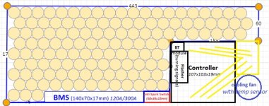
60V 32Ah Samsung 21700 40T (16s8p)
Flipsky 75100 VESC controller - max continuous 100A x2
New engine power cable 4 mm² + temp. sensor x2

Battery:
Samsung 40T cells seem to be the best choice. Any pros or cons? Which BMS should I choose (most of them are wider than the cell)? If the controller has max continuous power 200A (100A per wheel), the BMS must also have 200A? Because I saw 300A controllers connected to 150A BMS. Confusing 😅

Controller:
I like the Flipsky controller because of its size (11 x 11 x 2 cm) and these based on VESC are the best, right? Has anyone tried to connect a dashboard to it? Any advice? (I think the hardest part for me, including fitting the throttle and brake sensors).

I also considered the Nucular controller, but the waiting time is approx. 7 months. Kelly controllers are kinda big. Stormcore and Trampa are max 60V. Have I missed something? Is there any good kit with dashboard so I don't have to mess with all of this?

I will also have to do a 12V installation to power the lights and horn, but that should be relatively easy. Led flasher for turn signals and just new wires for buttons located on the steering wheel.

Hub motor:
Thicker cable + temperature sensor connected to the controller (if possible?) + ferrofluid statorade to improve cooling and get the maximum out of the motors, because I think they will be the main limitation here?

This is my first time so any advice and ideas are welcome :)
 
Oskar,
I read your whole post (because I was searching info on Kelly controllers) before realizing nobody had responded yet.... While you have laid out some good plans, you didn't state what are your ultimate goals...

Should I stay at 60V and increase the battery capacity or increase the voltage to 72V and stay at the same capacity? What do you think?

If you state that you want to go faster or you want to go twice as far, then someone will hopefully help you out. The general rule is more voltage for more speed, and more amps for more distance....

Best of luck,
Keith
 
Dunlop said:
If you state that you want to go faster or you want to go twice as far, then someone will hopefully help you out. The general rule is more voltage for more speed, and more amps for more distance...

Thanks for your reply Keith. Well I already know that 128 cells (16s8p) is the total max that I can fit there and there is no chance for 140 cells. So I guess I'll stay at 60V because 72V in a 20s6p configuration is pointless.

So even if I use 40T cells with a 200A controller (vs 70A stock) and a 120A/300A battery BMS (vs 80A), the performance will remain the same?
 

Attachments

  • 60V32Ah-16s8p.jpg
    60V32Ah-16s8p.jpg
    81.3 KB · Views: 1,799
Moderator advice to all readers:

Cheez posts consistently dangerously incorrect information and advice that could lead to fire and death (in regards to batteries, etc).

Other information is simply incorrect and could lead to wasted money and severe dissatisfaction.

Do not follow any of their advice or information.


Original complete post below:
____________________

Oskar said:
Hey, I own a Vsett 10 electric scooter and would like to replace the battery and controller, but I need your help guys :)

Now:
60V 28Ah Samsung 18650 (???)
Controller 30-35A x2
Hub motor 60V 1400W (3 mm² cable) x2

Plan:
60V 32Ah Samsung 21700 40T (16s9p)
Flipsky 75100 VESC controller - max continuous 100A x2
New engine power cable 4 mm² + temp. sensor

Battery:
Samsung 40T cells seem to be the best choice. Any pros or cons?
There is no cons on the Samsung T cells... They are the best out there due to very high current discharge with minimal resistance. Will work great even in the cold/freezing as they don't drop power at load. Unlike most other competing brands and models the Samsung T cells (30T and 40T) actually give you that current you ask for, to get all out of the battery. They are very discharge-friendly. Most other cells, including Molicel P42A, require HUGE amount of force to draw the current out of them, needing a controller that is rated at 200A or even 500A on a typical 40- 45 Ah battery pack... Samsung 50E cells are also good example. You will need very powerful controllers to get all power out of those cells. Will need something like 200+A controller to actually draw 120A out of a 50E battery pack. In other words you won't get true 120A using a 120A controller because they don't like to be discharged at anywhere near max advertised rate. Samsung 40T cells will give you the amp you want without having to use powerful controllers because they don't have this limitation. It's pretty much the best out there. That 30A discharge on the 40T cells is not the max. The maximum discharge current is 45A (the datasheet doesn't state this), and the 30T cell is 50A max.
The problem with other batteries is that if you forcibly draw max current out of them you will damage the cells, leading to premature failure.

I guess there is a small con to the Samsung T cells, poor fuel economy. Because they liked to be so easily discharged you will need to make ways to draw less power. Using the 200A controller (2x100A) would be a bad idea because the battery will run out very fast if you go fast. 200 true amp that the cells will give you, will get you over 100 mph on a scooter like yours. Use a controller that draws 4 times less, 50A total would give you good range. You will be surprised how fast you will go with just 50 true amp.

Which BMS should I choose (most of them are wider than the cell)? If the controller has max continuous power 200A (100A per wheel), the BMS must also have 200A? Because I saw 300A controllers connected to 150A BMS. Confusing 😅
It's possible to run 300A controller with 150A BMS because it can't actually draw 300A nor 200A because the batteries can't give you that current anyway because of the limitation I explained earlier. It's better to use BMS that can handle more amp than the controller can draw..

Controller:
I like the Flipsky controller because of its size (11 x 11 x 2 cm) and these based on VESC are the best, right? Has anyone tried to connect a dashboard to it? Any advice? (I think the hardest part for me, including fitting the throttle and brake sensors).
I am not sure about that controller.. I would go with a Sinewave controller which will be more energy efficient (increased range) and will give you even higher top end speed.

Hub motor:
Thicker cable + temperature sensor connected to the controller (if possible?) + ferrofluid statorade to improve cooling and get the maximum out of the motors, because I think they will be the main limitation here?
Yeah thick copper conductors in the wire going to these motors would be good as that will be the limiting factor when going 100A or greater.. Also make sure to use 99.9% copper connectors for connecting those battery wires and the phase cables from the motor.

I looked at the diagram of your scooter deck space for the battery pack to fit... Seems like your deck is small. May be a good idea to mount the controller on the outside of the deck, on the side. That way you will have more room for batteries. 60V system would be fine. I would go 18 series instead of 16 series to make more headroom for voltage and for longevity purpose.
 
https://endless-sphere.com/forums/viewtopic.php?f=35&t=115280

Have you considered a deck spacer and make it all battery underneath? External controllers will also cool better. Think Kaabo Wolf King GT.
 
Thanks for your post cheez :)

cheez said:
There is no cons on the Samsung T cells... They are the best out there due to very high current discharge with minimal resistance. Will work great even in the cold/freezing as they don't drop power at load. Unlike most other competing brands and models the Samsung T cells (30T and 40T) actually give you that current you ask for, to get all out of the battery. They are very discharge-friendly.

All the fastest/most expensive electric scooters use 40T cells, so I was pretty sure it was the best choice ;)

I guess there is a small con to the Samsung T cells, poor fuel economy. Because they liked to be so easily discharged you will need to make ways to draw less power. Using the 200A controller (2x100A) would be a bad idea because the battery will run out very fast if you go fast. 200 true amp that the cells will give you, will get you over 100 mph on a scooter like yours. Use a controller that draws 4 times less, 50A total would give you good range. You will be surprised how fast you will go with just 50 true amp.

Then it seems to me that changing the controller would not make sense if now the power is 2x 30A (35A max). There will be a lot of work connecting the lights, turn signals and other things running on 12V. But I'm not sure if replacing only the battery (and keep stock controller) is enough to noticeably change the performance of the scooter?

It's possible to run 300A controller with 150A BMS because it can't actually draw 300A nor 200A because the batteries can't give you that current anyway because of the limitation I explained earlier. It's better to use BMS that can handle more amp than the controller can draw..

Okay, so that sounds like 320A/140A BMS that's more than I need. Good, because many of them are wider than 8 cm and I would have a problem to fit them under the deck.

I am not sure about that controller.. I would go with a Sinewave controller which will be more energy efficient (increased range) and will give you even higher top end speed.

Flipsky controller supports square wave and sine wave modes. I read that I can't even use a square wave controller because it won't work with my hall sensor motors, right?

The controller is completely programmable and customizable, I'm not going to use its full power (2x100A) all the time, you can create multiple profiles in the application and find the best setting for performance and range.

Screenshot_20220916-213321~2.png

Yeah thick copper conductors in the wire going to these motors would be good as that will be the limiting factor when going 100A or greater.. Also make sure to use 99.9% copper connectors for connecting those battery wires and the phase cables from the motor.

Thanks for the important advice regarding connectors 👌🏻

I looked at the diagram of your scooter deck space for the battery pack to fit... Seems like your deck is small. May be a good idea to mount the controller on the outside of the deck, on the side. That way you will have more room for batteries. 60V system would be fine. I would go 18 series instead of 16 series to make more headroom for voltage and for longevity purpose.

Nooo, I really don't like what it looks like 😅 I think I'll get an extra external battery (16s2p / 8Ah) connected by the second charging port only to extend the range when I need it 🤔 40Ah should be enough not to see a drop in range.

But I have one question - should the external battery BMS have the same power as the main one?
 
Excuse a newbies confusion, but cheez says it is ok for the controller to ask for more amps than the battery can provide. I thought a battery should have a higher rating.
 
Tfisher309 said:
Excuse a newbies confusion, but cheez says it is ok for the controller to ask for more amps than the battery can provide. I thought a battery should have a higher rating.

You are correct--a battery should always be *at least* capable of the demand placed on it, and never loaded beyond it's abilities.

This really means a battery on a new system must be significantly more capable than the system will be able to demand of it, because as the battery degrades over time it will become less capable.

If it starts out only just capable of system demands, then as it degrades it's being stressed by overloading, starting essentially from day one, and increasingly problematic as time goes on. :(
 
Moderator advice to all readers:

Cheez posts consistently dangerously incorrect information and advice that could lead to fire and death (in regards to batteries, etc).

Other information is simply incorrect and could lead to wasted money and severe dissatisfaction.

Do not follow any of their advice or information.


Original complete post below:
____________________

Oskar said:
Then it seems to me that changing the controller would not make sense if now the power is 2x 30A (35A max). There will be a lot of work connecting the lights, turn signals and other things running on 12V. But I'm not sure if replacing only the battery (and keep stock controller) is enough to noticeably change the performance of the scooter?
I am afraid those stock controllers (most scooters out there) are junk, as they lack in cooling. They run hot and lose power if continuous load is applied. Aftermarket controller (usually bigger in physical size) would be the better way to go. 60A using Samsung 40T cells will be different than 60A using other batteries like Samsung 50E or most others because the 40T cells not only have enough headroom in current they also run cool so you get more clean power out of those. Just make sure you apply plenty of high purity copper materials to connect these batteries so that the connections themselves don't become the limiting factor. With just 50A you can go 65- 70+ true mph if you aren't very heavy.


Flipsky controller supports square wave and sine wave modes. I read that I can't even use a square wave controller because it won't work with my hall sensor motors, right?

The controller is completely programmable and customizable, I'm not going to use its full power (2x100A) all the time, you can create multiple profiles in the application and find the best setting for performance and range.
That's good. It's nice it provides you full range of voltages so you don't have to worry about low voltage and high voltage cut-off.. Can you adjust the amp as well? If not adjustable, I guess you could just use your gears to control the power. The Samsung 40T, because it has such high headroom in current and efficiency, you can get good range out of them if you go at moderate speed, it will be more efficient than other batteries so your range will increase.

Your project will be very cool.. How many 40T cells can you fit in your deck?

But I have one question - should the external battery BMS have the same power as the main one?
Yes keep the BMS discharging limit the same as the main one.
 
Moderator advice to all readers:

Cheez posts consistently dangerously incorrect information and advice that could lead to fire and death (in regards to batteries, etc).

Other information is simply incorrect and could lead to wasted money and severe dissatisfaction.

Do not follow any of their advice or information.


Original complete post below:
____________________

Oskar, one more note I wanted to make. I would not recommend using dual controllers and dual motors. It appears the Flipsky controller is a single controller, can output to two motors. Splitting power into two motors is not very safe, as they are independently managed per motor for safe power delivery. Dual controllers (not yours, but the dual controllers in general) will cause voltage spikes during load due to imbalance of the power delivery. They usually damage motors as a result. So I would recommend going a single RWD...
 
cheez said:
Dual controllers (not yours, but the dual controllers in general) will cause voltage spikes during load due to imbalance of the power delivery.

From where are you pulling this nonsense? Controllers can make electrical noise, but all "spikes" (from constructive wave interference I guess?) if they even tried to form would be absorbed by the battery on one side or the motor's inductance on the other. Controllers easily resist any disruption caused by the electrical noise that a motor generates, batteries are big imperturbable pools of charge that slurp up any transient voltage gradients they're exposed to, and motors themselves eat whatever electrical energy comes at them and convert it into mechanical work and/or heat-- it's their job.

They usually damage motors as a result.

Oh for cripes' sake. Please back up this hogwash with data if you have it (you don't) and stop defecating in the pool of technical knowledge we have going here.

Making pseudo-technical stuff up isn't a smart person thing to do. It's the opposite.

Lots of us here, including my riding buddy, use dual motors with parallel controllers on the same battery. Both motors work just as well together as they do by themselves.
 
Moderator advice to all readers:

Cheez posts consistently dangerously incorrect information and advice that could lead to fire and death (in regards to batteries, etc).

Other information is simply incorrect and could lead to wasted money and severe dissatisfaction.

Do not follow any of their advice or information.


Original complete post below:
____________________

Chalo said:
cheez said:
Dual controllers (not yours, but the dual controllers in general) will cause voltage spikes during load due to imbalance of the power delivery.

From where are you pulling this nonsense? Controllers can make electrical noise, but all "spikes" (from constructive wave interference I guess?) if they even tried to form would be absorbed by the battery on one side or the motor's inductance on the other. Controllers easily resist any disruption caused by the electrical noise that a motor generates, batteries are big imperturbable pools of charge that slurp up any transient voltage gradients they're exposed to, and motors themselves eat whatever electrical energy comes at them and convert it into mechanical work and/or heat-- it's their job.

They usually damage motors as a result.

Oh for cripes' sake. Please back up this hogwash with data if you have it (you don't) and stop defecating in the pool of technical knowledge we have going here.

Making pseudo-technical stuff up isn't a smart person thing to do. It's the opposite.

Lots of us here, including my riding buddy, use dual motors with parallel controllers on the same battery. Both motors work just as well together as they do by themselves.
I'm talking about the sudden voltage spikes/fluctuations in large level not electrical "noise". Not all controllers are perfect. They sometimes fail to deliver the stable/tolerable voltages. The internals of the controllers aren't designed to run dual motors when two controllers are used. Single controller splitting power to dual motors are less of risk of such failure, but still not as safe as a single controller powering just one motor as it prevents sudden voltage drop/spike going between the front and rear motors.. The reason why the motors fail is commonly due to the use of dual controllers.
 
cheez said:
I'm talking about the sudden voltage spikes/fluctuations in large level not electrical "noise". Not all controllers are perfect. They sometimes fail to deliver the stable/tolerable voltages. The internals of the controllers aren't designed to run dual motors when two controllers are used. Single controller splitting power to dual motors are less of risk of such failure, but still not as safe as a single controller powering just one motor as it prevents sudden voltage drop/spike going between the front and rear motors.. The reason why the motors fail is commonly due to the use of dual controllers.

Again you're saying things that don't make sense, that don't correspond to real world experience, but not explaining them or offering any evidence to support them. Please stop shoveling untruths into this forum.

When a controller is powering a motor, both the battery and the motor are in the circuit. Batteries and motors are both exceptionally efficient sinks to dissipate any variations in bus voltage. You physically can't have more than a handful of millivolts of "spike" because it would disappear into the motor or the battery. If that's what you're saying, please explain. If that's not what you're saying, and you are asserting that a small fraction of a volt electrical blip is likely to damage a motor, please explain.

Don't just offer more variations of your fantasy alternate-universe electrical engineering. Explain to us how a motor that's designed to absorb and convert tens of amps and dozens of volts into mechanical force would be damaged by tiny variations in voltage that you'd need an oscilloscope to find.
 
Tfisher309 said:
Excuse a newbies confusion, but cheez says it is ok for the controller to ask for more amps than the battery can provide. I thought a battery should have a higher rating.

Unfortunately Cheez has not learnt enough about ebikes to be offering correct advice so it would be wise to ignore anything of a technical nature from him until he has.

☠️☠️☠️
 
Curtis has a brother? Or a sock puppet?
 
Moderator advice to all readers:

Cheez posts consistently dangerously incorrect information and advice that could lead to fire and death (in regards to batteries, etc).

Other information is simply incorrect and could lead to wasted money and severe dissatisfaction.

Do not follow any of their advice or information.


Original complete post below:
____________________

nicobie said:
Tfisher309 said:
Excuse a newbies confusion, but cheez says it is ok for the controller to ask for more amps than the battery can provide. I thought a battery should have a higher rating.

Unfortunately Cheez has not learnt enough about ebikes to be offering correct advice so it would be wise to ignore anything of a technical nature from him until he has.

☠️☠️☠️
I said "It's possible to run 300A controller with 150A BMS because it can't actually draw 300A nor 200A because the batteries can't give you that current anyway.."

Let me give you an example.

You have a 400A controller. You have a 150A discharge limit on BMS. You have a 9P Samsung 50E battery pack (Weped FS would be a good example). But the battery pack can only putout 132.3A...as that is the limitation of the battery. Long before you even reached the limit of what the BMS can support failed to produce that 400A you asked for...

Most battery cells can't give you high current. A 15.5A max peak current rated battery cell like the Samsung 50E can't give you that amp you ask for as they don't like to be drawn high current. You have to "force" it by using more powerful controllers that can draw much more amp. You would need a 400A (or 2 x 200A) controller to draw near max peak current of 14.7A per cell in a battery pack. That equates to 132.2A. The BMS is likely 150A rated. This isn't the only case, there are many other batteries that can't give you such high current unless you force it using very high current drawing controllers.. You are not going to get 130A out of the battery with a 130A controller...nor can you get 80A out of this battery with an 80A controller because the of limitation of the battery cells.

I also said that you "should" use a BMS that can handle higher amp than the controllers can draw.
 
Moderator advice to all readers:

Cheez posts consistently dangerously incorrect information and advice that could lead to fire and death (in regards to batteries, etc).

Other information is simply incorrect and could lead to wasted money and severe dissatisfaction.

Do not follow any of their advice or information.


Original complete post below:
____________________

Chalo said:
You physically can't have more than a handful of millivolts of "spike" because it would disappear into the motor or the battery.
I am afraid it's way more than just "millivolts" of spikes. It's massive, sudden drop of voltage that will damage the motor. And I did not say the physical magnet of the motor will get damaged, but the electronics inside the motor will get damaged. It becomes problematic as you put great load on the controller and battery (pushing 50- 100+ amp) the more aggressive that voltage spike can happen and greater risk of getting the motor(s) damaged. If you are talking a small scooter with a little battery and baby controllers running dual motors is at less of risk because the less power is drawn.


.
 
cheez said:
Chalo said:
You physically can't have more than a handful of millivolts of "spike" because it would disappear into the motor or the battery.
I am afraid it's way more than just "millivolts" of spikes. It's massive, sudden drop of voltage that will damage the motor. And I did not say the physical magnet of the motor will get damaged, but the electronics inside the motor will get damaged.

The motors I've opened up have nothing inside that could be characterized as "electronics" besides three Hall effect sensors. (Those are on a separate 5V bus.) Everything else is big copper, magnets, back iron, bearings, and structural components.

What part of a motor exactly are you suggesting could be damaged by a drop in voltage?

Please stop polluting the forum with untrue information. You're doing a huge disservice to any neophyte who takes your garbage seriously.
 
Chalo said:
The motors I've opened up have nothing inside that could be characterized as "electronics" besides three Hall effect sensors. (Those are on a separate 5V bus.) Everything else is big copper, magnets, back iron, bearings, and structural components.

What part of a motor exactly are you suggesting could be damaged by a drop in voltage?
Yes, the Hall Effect sensor in the motor.


.
 
cheez said:
Chalo said:
The motors I've opened up have nothing inside that could be characterized as "electronics" besides three Hall effect sensors. (Those are on a separate 5V bus.) Everything else is big copper, magnets, back iron, bearings, and structural components.

What part of a motor exactly are you suggesting could be damaged by a drop in voltage?
Yes, the Hall Effect sensor in the motor.

How?! It's not on the motor power circuit in any way. Are you saying dual controllers interfere somehow with the separate 5V supplies to the Hall sensors? If so, how? And how could they possibly be harmed by a drop in voltage anyway? You're chatting nonsense again.
 
First of all, please forgive me the late reply. I spent the last 3 weeks in hospital and had two kinda complicated leg surgeries. Everything went well so I'm going to finish my project :thumb:


cheez said:
With just 50A you can go 65- 70+ true mph if you aren't very heavy.

I don't think that's entirely correct information. My second scooter (I'm still waiting for it) with a 72V battery (40T cells) + two Kelly's controllers (2x 200A) will have V max 145 km/h. So I will be happy if I can exceed 100 km/h here :D

cheez said:
Can you adjust the amp as well?
(...)
Your project will be very cool.. How many 40T cells can you fit in your deck?

Yes of course, I can adjust the amp. 128 cells (16s8p).

Chalo said:
Withmotors themselves eat whatever electrical energy comes at them and convert it into mechanical work and/or heat-- it's their job

That's exactly what I've always heard, that the extra energy will just be converted into heat :flame: that's why I'm going to add ferrofluid to the motors to help cool them down a bit

Chalo said:
How?! It's not on the motor power circuit in any way. Are you saying dual controllers interfere somehow with the separate 5V supplies to the Hall sensors? If so, how? And how could they possibly be harmed by a drop in voltage anyway?

So I don't have to worry about damaging the Hall sensors? And if I add ferrofluid and temp sensors connected to the controller that constantly check the temperature, will I be safe? As the motors are rated for 60V 1400W (2100W peak), I am worried about them the most :roll: I will definitely change the cables to thicker ones
 
Oskar said:
So I don't have to worry about damaging the Hall sensors?
Not from voltage, assuming all normal conditions and no wiring damage/etc...though heat certainly affects them. :)


And if I add ferrofluid and temp sensors connected to the controller that constantly check the temperature, will I be safe? As the motors are rated for 60V 1400W (2100W peak), I am worried about them the most :roll:
As long as the temperature sensors correctly report the temperature (meaning, they are the right kind to match what the controllers can read, as there are many kinds of sensors), and they are placed in the right spot (often right under the windings on the side of the stator, where heat peaks the highest and fastest), and the controllers can correctly limit the motor power / current vs temperature and are set up to do so.

Motor wattage ratings don't necessarily mean much; some of them are sold as higher wattage than designed for, and some are sold as far less than they can handle, and it also depends on the conditions they're used under, etc. (See http://ebikes.ca for some articles with useful info, including one on motor power ratings).

The simulator at http://ebikes.ca/tools/simulator.html can help you determine the power needed to do the job you need the system to do for you (even if you use preprogrammed parts different from what you are going to use, the power demands will be similar) Then you can see what the hardware you have (or need to get) must be able to handle.
 
Moderator advice to all readers:

Cheez posts consistently dangerously incorrect information and advice that could lead to fire and death (in regards to batteries, etc).

Other information is simply incorrect and could lead to wasted money and severe dissatisfaction.

Do not follow any of their advice or information.


Original complete post below:
____________________


Oskar said:
cheez said:
With just 50A you can go 65- 70+ true mph if you aren't very heavy.

I don't think that's entirely correct information. My second scooter (I'm still waiting for it) with a 72V battery (40T cells) + two Kelly's controllers (2x 200A) will have V max 145 km/h. So I will be happy if I can exceed 100 km/h here :D
Most wattage and amp rating on scooters out there are highly overrated. They are not anywhere near realistic figure. You don't need true 8000 watts to get to 60+ mph.
The real big matter is that most li-ion 18650 or 21700 batteries don't give you much amp. Most batteries don't like to be discharged at high current. You will need more powerful controllers to draw high amps out of these batteries by force. You buy or build battery pack using LG M50T or Samsung 50E or LG MJ1 cells (typical 7- 8p parallel connections) and use an 80 amp controller and expect to get 80 amp.. You are not going to get 80 amp nor anywhere near it. You will need a controller that draws at least 150 amp to get 80 amp out of the batteries. Another problem is that due to poor connections in the battery pack (they use either nickel or fake nickel thin strip spot welded) it adds resistance and heat, converting energy into waste, unusable energy. There is more to that. Those batteries create high resistance within the cells themselves so they don't provide clean power at very high current either, only at low current. Most scooters out there have these issues so they don't provide true power anywhere near what they advertised. The only ones that can actually provide power closest to what is advertised are the Samsung 40T and 30T (genuine) cells. You don't need powerful controller to draw 50 amp or 100 amp or 150 amp and so on, as long as you provide enough of conductive materials to connect these batteries inside the pack. Your battery connections will become the bottleneck not the battery. With the Samsung T cells 50 amp controller will draw 50 amp or 100 amp controller draws 100 amp in this case. In other words you can easily smoke an advertised 80A~ 100A rated scooters with your scooter with hand-built Samsung 40T battery pack and a 50 amp controller. I am not telling you you have to go with the 50 amp setup. You can go higher if you want. But if setup right, that 50 amp will give you speed you never thought you could possibly achieve... If you go past 60 amp I would recommend you use 99.9% copper bars and high-grade silver paste epoxy to connect these batteries. Spot welding is no good as it does not provide enough contact for electrical conductivity and can't weld copper strip/bars anyway. Soldering is also no good because it limits current (bunch of resistance) as the soldering material is worse than the pure nickel.


cheez
 
Back
Top