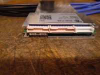
The ANT BMS wiring diagram shows the B- of BMS going to the Battery Negative. It shows the C- of the BMS going to the controller. I guess my question is, does the C- of the BMS basically become the Battery Negative?
Yeah, pretty much.
Can I make a piece of copper big enough to drill 2 holes and fasten 2 lug bolts securely to it then wrap it up after?
Sure, it's the best way to do it.
Oh 1 more question about wiring.
In the Kelly manual it shows that right after the key switch there is a fuse before it goes to PWR on the controller, but on the diagram(s) it shows 2 different rated fuses.
Diagram #1 - Section 3.2.2 page 18 of manual (full wiring): it shows a 2A fuse
Diagram #2 - Section 4.4 page 30 of manual (wiring of the Controller, Motor, Hall Sensors, Throttle, Key Switch, Main 400A Fuse, Battery Pack): it shows a 2-5A fuse
Anyone know if there is a reason for that? Should I just go with the 5A so I'm not blowing 2A fuses right and left?
I would try using the 2A fuse first.
If it bows up often for no reason then switch to a 5A.
Now I am just trying to think ahead for when I am setting my parameters for the BMS and controller.
The ANT BMS I ordered is rated for 340A continuous / 800+ peak for 30sec.
My controller is rated for 190A continuous / 360A peak for 1min.
What would be the best parameters to set the BMS and controller at for my 3kw QS hub motor so I am getting good power without killing anything.
Everything first depends on what your battery cells can deliver as far as maximum instant current.
Also, you say that the controller is rated at 360A peak but is this battery amps or phase amps?
I will assume the controller is rated at 190 battery amps for the rest of the example. Your battery is good for 500A peak so that's great. Continuous power doesn't really matter here because you will not run the bike at full throttle for an hour, there will be red lights and stops at some point.
So basically here the limiting factor is your controller. That means it will be the first thing that cuts off in case there is too much current being asked.
So if yout controller is set up at 190A battery current, and your battery is capable of 500Amps, then you can set your BMS to a maximum current of anything you want between 190A and 500A, it doesn't matter.
But I suggest leaving some margin, so in this case you should set up the BMS for at least 200A, otherwise the BMS might cut under full load. Personnally I'd set it up at 250A just to be sure it won't randomly trigger.
Anyway, what I mean is that the BMS current should be higher than the controller maximum current, always. But it must always stay within the limits of what your battery cells are capable to produce, otherwise it will not do its role to protect them.
*EDIT* I also found this Accelerator unit and cable line on Amazon:
I think it is similar to the one previously mentioned. I am thinking about getting it but I am not sure how to connect it or what to do. Would it be difficult to switch my current throttle to this style? Or is it plug and play. It looks like one end of the cable goes to the throttle, and the other end of the cable goes to the box. Then the small throttle wires just hook up the way they normally should right? I am a little confused.
View attachment 350996
Thanks everyone.
You will also need the handle.
This:


")