
I thought you were joking... What a great way to crimp for cheap!I use a hammer crimp. Much cheaper, and much fewer mechanical parts, very simple. It also works with a wide range of lug sizes, without having to change out jaws.
Downside: it's not portable, you have to secure it to a table and bring the cable to it, rather than bring the crimper to the cable. This might be a deal breaker if you need to crimp one end of the cable if the other end is unmovable, or something. Another downside, is that while it does work quite well, you have to use a pretty heavy hammer and smash it rather hard to get it to crimp.
Upside: you get to use a really big hammer and you get to smash something really hard.
-
Hello ES! We could use some help to get us past the finish line on building the new knowledgebase for the forum.
Can you donate? Please see our fundraising page. Thank you!
You are using an out of date browser. It may not display this or other websites correctly.
You should upgrade or use an alternative browser.
You should upgrade or use an alternative browser.
Battery build & Controller Upgrade
- Thread starter ElectricGSXR
- Start date
No, not joking at all. They really do work. You still have to size the lug to the cable appropriately; if you use too large of a lug it'll be easy for the cable to slip out. And you really do have to pound the s$&t out of it, maybe 2-3 times per side, with the largest hammer you have. And It'll look messy and uneven compared to hydraulic crimpers. But as long as you're okay with those downsides, the crimp is solid. I got mine for $15 a couple years ago, still does fine. Maybe at some point I'll splurge on a nice set of hydraulic crimpers, so I can make cables at places other than my workbench. But for now I'm good.I thought you were joking... What a great way to crimp for cheap!
(the hammer I'm using is like this one, basically a small sledgehammer)
A possibly useful thread

 endless-sphere.com
Mechanical Crimping Large Gauge Wiring Harnesses
Ive been trying to address a way to reach out to thehigh current and high performace crowd with my harness service while making my job easier. Im was trying to gauge how you guys felt about mechanical crimping. I found some 8G mechancial crimp splices. I figure it could take 4 12g or 10g on one...
ElectricGSXR
🔋 Established
I was able to get at the throttle wires today. The wires I have coming out of the throttle are:
red
black with white stripe
yellow
green with yellow stripe
black with red stripe
red with white stripe
brown with white stripe
dark blue or purple color
I'm not sure which ones are the throttle wires. I don't even know if this mish mash of wiring is original or if the old owner did things himself and changed the wire colors. I don't know what to do honestly.
Last edited:
ElectricGSXR
🔋 Established
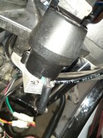
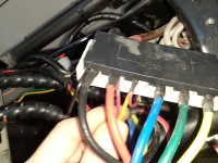
I tried to show the ignition wire mess as best I could.
Starts as 4 wires. Then only 2 get used but change color to yellow and red. Then gets spliced down the line into 2 red wires and 2 yellow wires.
1 red wire goes to the bus where it is attached to the main line power from from the breaker and going to the controller.
2nd red wire goes to the charge port on the bike.
1 yellow wire is attached to a small red wire about the same size. It goes to the controller with the hall sensor wires.
2nd yellow wire goes to the DC/DC converter.
I'm not sure which is the one would be considered the ignition wire. I think that it's the small red wire that is connected to the main power from the breaker from looking at the schematic but I'm not certain.
Attachments
Last edited:
Most controllers that have a KSI (keyswitch / ignition) input require battery voltage on that to turn on.
So if you have a thin wire from the main battery positive (in addition to the main thick battery positive) that goes to the controller via whatever circuitous route") then that is usually the KSI wire.
then that is usually the KSI wire.
If you have a switch on the system you want to wire in to turn off *just* the controller, this is the wire the switch would interrupt.
If you also want the switch to turn the DC-DC on/off, then you would interrupt the B+ between the battery and the point at which the DC-DC and controller KSI wires split from each other.
Regarding wires to/from the throttle, if they are not connected and operating already so you can measure voltages, you'd probably have to trace those out from inside the throttle to wherever they go on the bike.
What functions does the actual throttle unit have on it, besides the throttle? Knowing those we can make guesses as to what the wires' functions might be, and so the voltages/etc to look for.
So if you have a thin wire from the main battery positive (in addition to the main thick battery positive) that goes to the controller via whatever circuitous route
then that is usually the KSI wire. If you have a switch on the system you want to wire in to turn off *just* the controller, this is the wire the switch would interrupt.
If you also want the switch to turn the DC-DC on/off, then you would interrupt the B+ between the battery and the point at which the DC-DC and controller KSI wires split from each other.
Regarding wires to/from the throttle, if they are not connected and operating already so you can measure voltages, you'd probably have to trace those out from inside the throttle to wherever they go on the bike.
What functions does the actual throttle unit have on it, besides the throttle? Knowing those we can make guesses as to what the wires' functions might be, and so the voltages/etc to look for.
ElectricGSXR
🔋 Established
More pictures of the throttle here.Regarding wires to/from the throttle, if they are not connected and operating already so you can measure voltages, you'd probably have to trace those out from inside the throttle to wherever they go on the bike.
What functions does the actual throttle unit have on it, besides the throttle? Knowing those we can make guesses as to what the wires' functions might be, and so the voltages/etc to look for.
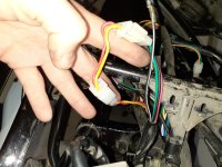
Ok there's some pictures showing the functions that are on the throttle and there is also a black wire there that isn't bunched with the others.
If I have to open up I will do it tomorrow when there is more time. It's later in the evening now.
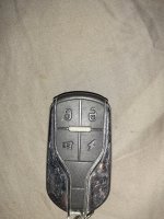
I'm not really sure what the functions are I can't recall using them often. It looks like different lighting controls but I'm not sure what the little lightning bolt switch is at the bottom I don't think it's connected it never did anything.
On the other handle are the turn signals, the D-P-N-R and the horn. I didn't take photos of that side tonight I can do so tomorrow sorry I rushed to get back in tonight.
I think I figured it out. Tell me if I'm wrong. Is the throttle just that single wire coming directly off the throttle? Duh lol
And maybe it's not a single wire I'm not really sure of that either it just looks like 1 but it could be more. I will check that tomorrow.
Attachments
Last edited:
Dui ni shuo de dui
🚴♂️ Mega poster
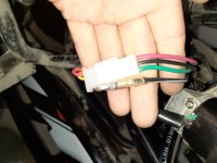
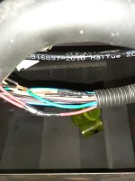
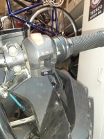
The throttle wire is this one, you should have three wires inside, most likely red/green/black:More pictures of the throttle here.
Ok there's some pictures showing the functions that are on the throttle and there is also a black wire there that isn't bunched with the others.
If I have to open up I will do it tomorrow when there is more time. It's later in the evening now.
I'm not really sure what the functions are I can't recall using them often. It looks like different lighting controls but I'm not sure what the little lightning bolt switch is at the bottom I don't think it's connected it never did anything.
On the other handle are the turn signals, the D-P-N-R and the horn. I didn't take photos of that side tonight I can do so tomorrow sorry I rushed to get back in tonight.
I think I figured it out. Tell me if I'm wrong. Is the throttle just that single wire coming directly off the throttle? Duh lol
And maybe it's not a single wire I'm not really sure of that either it just looks like 1 but it could be more. I will check that tomorrow.

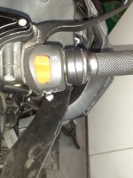
These are two separate things, in green it is the casing for the light switch modes and what usually is the ignition button in red (but it's just a button so any function can be wired onto it, for example on my bike I use this red button as a switch for wet/dry so I can limit the controller power when the road is slippery). The one at the bottom is usually the starter motor button for the gas engine bikes, but here again it is just a switch so you can wire anything on it. On my bike I wired the horn there (one horn button on each side).
Circled in orange is the throttle. Those are two separate, distinct units, the throttle you have is a cheap unit that comes with most ebikes, and the switch casing is a generic unit you can find on pretty much any motorcycle.

Personnally I do not like this kind of throttles because they are very exposed to rain. One time I was waiting at a red light under heavy rain and out of nowhere the bike started accelerating, because water found its way into the throttle. That was extremely scary. Also, these kind of throttles give a cheap feeling when driving, it's not nearly as pleasant as the ones in gas bikes.
So now on all my machines I'm using cable throttles, which is a regular motorcycle throttle assembly with a metal cable, and this cable is connected to a hall effect sensor that you can put somewhere inside the bike, where it won't get wet. Never had any issue since I installed these, and the driving experience is a whole lot better, it feels just like a real motorcycle throttle.
It's this kind of stuff:

For now you can keep the original throttle, but at some point replacing it with this thing would be a good idea.
Last edited:
Dui ni shuo de dui
🚴♂️ Mega poster
Based on the information you provided I would say this one is the ignition wire.1 yellow wire is attached to a small red wire about the same size. It goes to the controller with the hall sensor wires.
A simple test you can do is to make a continuity test with your multimeter (I assume you have one, right?).
Test between this wire"1 red wire goes to the bus where it is attached to the main line power from from the breaker and going to the controller."
and this wire (would have been clearer to label them 1-2-3-4 insead of 1-2 and 1-2):
"1 yellow wire is attached to a small red wire about the same size. It goes to the controller with the hall sensor wires."
Turn the key and you should have continuity between these wires, turn it the other way and there should be no continuity.
If it's the case then it's likely you just found the ignition wire.
If not, then maybe the ignition wiring is a little bit more complicated. In which case, please describe in details how you used to switch on the bike before, when the battery was still working.
Basically the ignition wire is just a wire that goes to the battery positive, through at least one switch, which usually is the key switch. Sometimes there can be several switches is series.
On your bike you also seem to have an alarm unit. That might complicate the wiring a little bit because the alarm has to cut ignition as well. I'm not an expert on these because I removed these useless alarms from all my bikes, I only rely on the key switch. Less stuff to worry about.
ElectricGSXR
🔋 Established
@Dui ni shuo de dui,
Let's call them R1 / R2 for the red and Y1 / Y2 for the yellow in order they are mentioned in the post.
So check R1 to Y1 with my multimeter. Will do that tomorrow.
But basically R1 goes the the bus and is connected in the same port as I think it's #6AWG wire that is going to the big wire side of the Yuyang King controller.
The Y1 goes on the other side of the controller where the smaller sized wires are.
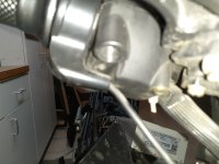
R1 is connected to I think #6AWG wire that goes to the controller on 1 side of a bus (I am calling it a bus but maybe it's not the correct term). On the other side of the bus it is connected to what is I think an audio cable that goes to the breaker. From the breaker it gets power from the anderson connector that plugs into the old battery's anderson connector. That's why I thought the ignition wire would be R1 because on the schematics it shows it going to the battery + and that's where I thought I traced it to. I showed it here:


Maybe what I'm trying to say makes more sense seeing a top view. You can see the audio cable I'm talking about better and the breaker it's going to. Other side of the breaker is that red wire that goes to the anderson connector which connected to the old battery.
Either way I will get it sorted tomorrow.
Thanks again my friend.
Let's call them R1 / R2 for the red and Y1 / Y2 for the yellow in order they are mentioned in the post.
So check R1 to Y1 with my multimeter. Will do that tomorrow.
But basically R1 goes the the bus and is connected in the same port as I think it's #6AWG wire that is going to the big wire side of the Yuyang King controller.
The Y1 goes on the other side of the controller where the smaller sized wires are.
R1 is connected to I think #6AWG wire that goes to the controller on 1 side of a bus (I am calling it a bus but maybe it's not the correct term). On the other side of the bus it is connected to what is I think an audio cable that goes to the breaker. From the breaker it gets power from the anderson connector that plugs into the old battery's anderson connector. That's why I thought the ignition wire would be R1 because on the schematics it shows it going to the battery + and that's where I thought I traced it to. I showed it here:
Maybe what I'm trying to say makes more sense seeing a top view. You can see the audio cable I'm talking about better and the breaker it's going to. Other side of the breaker is that red wire that goes to the anderson connector which connected to the old battery.
Either way I will get it sorted tomorrow.
Thanks again my friend.
Last edited:
ElectricGSXR
🔋 Established
"If not, then maybe the ignition wiring is a little bit more complicated. In which case, please describe in details how you used to switch on the bike before, when the battery was still working"
I always leave the breaker switch in the "on" position.
When I go to the store or something I use the FOB and press the button that activates the alarm. (someone tried to jam something in my key hole and turn it I can see damage so I think it's good to have the alarm)
So I use the alarm when I am out if I stop anywhere or go inside a shop. Parked inside my garage I do not arm the alarm system.
To switch on the bike I would disarm the alarm if it's active, the alarm would make a noise to say the alarm is disarmed. I put in the key and turn it on. Bike starts up.
I am almost certain that would be the sequence but I haven't done it in a while so maybe I am missing some small detail.
I hope this helps. Thanks again!
Last edited:
ElectricGSXR
🔋 Established
ElectricGSXR
🔋 Established
In the controller manual it says I will need insulated tools.
I have insulated screwdrivers but I was wondering if there was any other ones you guys might recommend I get for the job? I am just putting together the 10 leaf modules in series. They use a m6 nut on the modules.
I'm not sure what the size they use on the top of the Kelly controller but I can inquire about that.
Deliveries should start arriving this week and next. I want to try to have things ready to go so I can just start working..
Maybe insulated nut drivers might be a good idea?
ElectricGSXR
🔋 Established
I can't seem to find the ANT BMS app on the android / google play. Not sure what to do. I'd like to have the app on my phone.
Is the alarm just an alarm, or is it something that disables the system until it is disarmed?
The latter means it's wired in so that it can disconnect a signal or signals or power, etc., from something critical on the system, and you'd need to know what that is, if it's not working.
If it's working, then you should simply be able to disarm the alarm, connect the keyswitch output wire to the KSI wire on the controller, and the system should turn on. If that's not happening, let us know and we can suggest tests.
Insulated tools can be made by putting heatshrink over as much of the tool shaft as possible. You can use multiple layers for safety so if one gets nicked there's another under it. The reason for using them is so you can't short between any live connections. If you are not working on a battery, then they're not necessary as you simply disconnect the battery. Working on the battery is much safer with them, though, so if you drop the tool across conductors it's much less likely to cause an instant plasma fire ( i.e.: Electric Vehicle Discussion List - How Plasma Boy Got His Name :/ ).
There should be some links to apk's for the ANT BMS apps here on ES in various threads about it; might even be some actual attached zip files.
floydr
⚡ Regular
I can't seem to find the ANT BMS app on the android / google play.
ElectricGSXR
🔋 Established
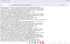
I downloaded it and got the apk file but its just a bunch of text I'm not sure what to dolater floyd
floydr
⚡ Regular
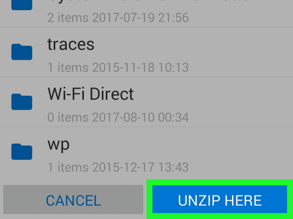
Please post a screen grab of the text. it is a .rar file did you download it to your phone or a computer? if a windows computer I think winzip will unpack it to the apk , it has been a while since I dealt with a .rar file on a android phone.
 www.wikihow.com

 www.ezyzip.com
later floyd
How to Open (Extract, Unpack) Zip, Rar and 7z Archives on Android
This wikiHow article teaches you how to view, open, and extract the contents of ZIP, RAR, and 7z folders while using an Android device. In order to do this, you must first download the folder in question onto your Android. Open your...
www.wikihow.com
How To Open RAR Files on Android (3 Methods)
Master the art of opening RAR files on Android with our step-by-step guide. Swing through the RAR jungle effortlessly with apps and online tools!
www.ezyzip.com
later floyd
ElectricGSXR
🔋 Established
ElectricGSXR
🔋 Established
I can't get anything to work
If you can't unzip/unrar the file, then I've attached it here as the actual apk file, but renamed to .zip. To use it, you need to change .zip to .apk
then you use whatever method your android device has for installing local apk files.
If it still doesn't work, then the apk is probably corrupt or incompatible with your android OS version.
then you use whatever method your android device has for installing local apk files.
If it still doesn't work, then the apk is probably corrupt or incompatible with your android OS version.
Attachments
ElectricGSXR
🔋 Established
ElectricGSXR
🔋 Established
Oh I might be on to something here now 1 sec
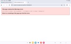
Well, you don't want to open it in your browser, you want to save it to your computer or device. A browser will probably complain at a 12 megabyte single-file webpage that isn't a webpage.
ElectricGSXR
🔋 Established
Yeah I saved it to my tablet and I tried to convert it on Ezyzip but I can't figure it out.
Why is it so hard to get the app what the hell I should be able to just download from google like it lets me for apple.
I've been trying to get it downloaded for over 5 hours now. Starting to have regrets on going with this bms. Now I have to rely on the scan thing working or I won't have access to the app which is why I wanted to build the battery in the first place.
As of right now I do not recommend ANT BMS to anyone that reads this. I might have to return it if I can't get the app to work. Batteries will be just sitting around. I hope I can figure this out or the scan thing works. Fingers crossed.
Last edited:
Similar threads
- Replies
- 19
- Views
- 934
- Replies
- 41
- Views
- 2,024
- Replies
- 21
- Views
- 2,139
- Replies
- 10
- Views
- 549
- Replies
- 16
- Views
- 2,729