Hey guys,
I have some questions involving wiring and also programming.
Wiring first.
I'm a little confused with the wiring diagram for the controller. In the Kelly manual (wiring diagram) it shows the Battery Negative going to the controller, but they don't show a BMS anywhere.
I am trying to draw my own diagram to understand it better also to take certain things I'm not using out like the contactor.
I am just wondering:
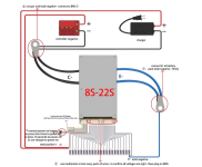
The ANT BMS wiring diagram shows the B- of BMS going to the Battery Negative. It shows the C- of the BMS going to the controller. I guess my question is, does the C- of the BMS basically become the Battery Negative?
Sorry if I sound crazy I am just a little confused.
Also I am wondering if I can make my own little copper "bus bars" to make multiple connections on. For example (in the ANT BMS wiring diagram) the C- of the BMS goes to the controller(-) but also to the charger/charging port(-) on bike in my case.
Can I make a piece of copper big enough to drill 2 holes and fasten 2 lug bolts securely to it then wrap it up after?
I am trying to clean up the wiring on paper first. I'm getting rid of the 100A breaker on my bike, and I'd like to actually get rid of that plastic "bus bar" too, even though I said I wanted to re-use it. I might get rid of the alarm if it gives me too much of a headache. I think I will be better off without that stuff for keeping the wires tidy and it not looking like spaghetti in there.
Oh 1 more question about wiring.
In the Kelly manual it shows that right after the key switch there is a fuse before it goes to PWR on the controller, but on the diagram(s) it shows 2 different rated fuses.
Diagram #1 - Section 3.2.2 page 18 of manual (full wiring): it shows a 2A fuse
Diagram #2 - Section 4.4 page 30 of manual (wiring of the Controller, Motor, Hall Sensors, Throttle, Key Switch, Main 400A Fuse, Battery Pack): it shows a 2-5A fuse
Anyone know if there is a reason for that? Should I just go with the 5A so I'm not blowing 2A fuses right and left? Not sure figured I'd ask if anyone knows why they have 2 options.
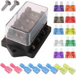
*EDIT* Here is a picture of a 4-way fuse holder. Maybe that would be useful if I need multiple size fuses?

*EDIT* Here is a link for the controller manual (can't seem to copy/paste individual pics from it sorry):
*EDIT*ANT BMS wiring diagram:

Now I am just trying to think ahead for when I am setting my parameters for the BMS and controller.
The ANT BMS I ordered is rated for 340A continuous / 800+ peak for 30sec.
My controller is rated for 190A continuous / 360A peak for 1min.
What would be the best parameters to set the BMS and controller at for my 3kw QS hub motor so I am getting good power without killing anything. I have the Nissan Leaf modules. I believe they are good for 200A continuous and they can peak out around 500A, I read here in a spec sheet someone had posted but I do not know 100% for certain if that was confirmed. I can't find a full data/spec sheet for them. I am sure they have a good enough output though. I'm assuming they are capable enough for my needs.
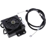
*EDIT* I also found this Accelerator unit and cable line on Amazon:
I think it is similar to the one previously mentioned. I am thinking about getting it but I am not sure how to connect it or what to do. Would it be difficult to switch my current throttle to this style? Or is it plug and play. It looks like one end of the cable goes to the throttle, and the other end of the cable goes to the box. Then the small throttle wires just hook up the way they normally should right? I am a little confused.

Thanks everyone.


