Definitive Tests on the Heating and Cooling of Hub Motors

justin_le

Administrator
Staff member
Joined
May 28, 2007
Messages
2,310
Location
Vancouver
Hey guys, so I've been meaning for a long, long time now to run a set of controlled lab experiments measuring the temperature rise of hub motors being subject to different load conditions. The main objective is to develop a more comprehensive 2nd order thermal model to incorporate into the ebikes.ca simulator program for predicting the overheating and failure times of a motor. However, it will also be a great opportunity to compare decisively the effect of different cooling strategies (vent holes, active fan blades, oil filled cooling etc.) in order to quantify and model their effects too. There's been a lot of neat pioneering work by people on this forum here (not to mention a lot of lively debate), but not quite as much empirical science.

As a background, the current "overheat in" time on the simulator comes from data gathered when heating up a static, non-rotating hub motor by putting a constant current into the phase winding, and then recording the phase voltage over time. Because copper has a well characterized temperature coefficient of resistance, as the temperature increases so too does the terminal voltage when fed with a constant current supply, and so the actual copper winding temperature was easily deduced without any thermometer devices.

The process and some of the data is shown in the post here:
http://endless-sphere.com/forums/viewtopic.php?p=218321#p218321

When the experiment is done at one current, the resulting temperature rise of the motor core models accurately enough as a single lump heat capacity with a heat conductivity to ambient. And by doing a linear regression, we could get a best fit coefficients for the equivalent heat capacity and conductivity that results in the smallest error to the actual data:
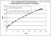
9C Thermal Model.gif

However, in addition to the fact that the motor isn't spinning which ought to greatly help with the convective cooling, this first order model also suffers from the fact that the copper windings, stator, and side cover are all lumped together and assumed to be at uniform temperature. But we know that there is quite a barrier between the stator and the side plates and their temperatures are anything but equal.

So in a more realistic situation, we would split the motor into two thermal masses. There is the stator core with the copper windings where the heat is generated, surrounded by the motor shell with it's own heat capacity. There would be one coefficient for heat transfer from the stator to the shell, and another coefficient for the transfer of energy from the shell to ambient:

 
So, this is the setup that I've put together on the dyno bench in order to get a more comprehensive picture:

View attachment 2

I'm using a 10x6 winding 9C hub as the basic test motor, because we have number of spare side covers which will make it easy to machine units with different venting/cooling strategies. The motor is direct coupled to a 5302 that I have powered from a servo controller that enables it to run at constant RPM during the testing, regardless of the load. The motor casing temperature is monitored with a USB IR temperature sensor from Omega:
http://www.omega.com/pptst/IR-USB.html

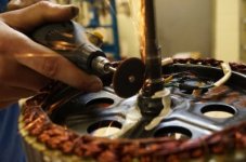
It wasn't cheap but at least it should be lab grade accurate and conveniently logs temperature data at 1Hz to a computer. Then for the inside motor winding temperatures, we ground some slits in the axle as others here have done and used these grooves to embed some 10K thermistors, one directly on the copper and another just under the lamination stack:
Thermistor Axle Slot Grinding.jpg


The rest of the setup is using a 40A controller and a Cycle Analyst logging the battery current and stator temperature.
 
Wow, this is great. I'm really interested in the data on this, since I am using a 9c 10x6 with a temp probe at the windings! If it helps you any, I computed the volume within the motor in this thread about 2/3rds of the way down the page... I came out with 1300ml, so 650ml is fluid right to the axle.

http://endless-sphere.com/forums/viewtopic.php?f=30&t=38039&start=25

Subscribed.

Edit: My data is for the 9c with squared off covers, sorry.
 
Subscribed.

I am doing very similar testing on RC style motors. Running them at a constant load on a dyno for ~10-15 minutes, monitoring the temperature, then extrapolating the data to find the equilibrium temperature above ambient for both motor and controller. The results showed that motor temperature rise was dictate by the torque rather than the power. The ESC temperature was really interesting, with most of the ebike controllers failing to handle sustained partial throttle. But those with synchronous rectification faired much much better. But at very low speeds I found some controllers again had significant heating issues, as I assume they did not have phase current measurement, or control. So the low BEMF, high load situation caused them issues.

Looking forward to your results. Would be interesting if you could also monitor your controller temperatures, if you run them in current limitting/partial throttle for sustain runs.

Keep up the good work.

- Adrian
 
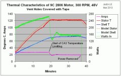
OK, so the first set of tests was just to validate the process and equipment a bit. I covered up all of the vent holes with dark masking tape to simulate an undrilled side cover, spun up the dynamo to 300 RPM, then ran the 9C 2806 motor off a 48V bench supply using a field-oriented controller set to 40A peak phase current.

Covered Vent Hole Test.jpg

The green line is the estimated wattage going into the hub based on the assumed phase resistance of the winding deduced from the stator temperature and the room temp winding resistance, so the power is increasing throughout the experiment. Then at just before 20 minutes, you see the power suddenly drops down by 40% and the motor core temperature levels off at just over 120 degrees. I was really perplexed when I first saw this, then I realized I had left the CA3 being used for the datalogging with the default values for thermal rollback, which is to start rollback at 90oC and fall to zero at 130oC. And with the default current limit left at 99A, that means the CA current limit at 122 degrees would be (99*(130-122)/(130-90) = 20 amps, which is exactly where it stabilizes at after a small overshoot. So that was an interesting side incident.

In any case, I then made an excel formula of the predicted temperatures based on the above model, and played around with the numbers until the shape of the curves matched the actual data pretty well. The model lines in the above graph come from the following coefficients:
Code:
Rwinding    0.145 Ohm
kV          0.097 V/RPM
C_stator    1400 J/deg
C_shell     1100 J/deg
1/R_stator  3.50 W/deg
1/R_shell   3.00 W/deg

One thing that you'll notice is that the shell temperature falls pretty much exactly midway between the motor core temperature and ambient temperature, and that the thermal resistance for heat to flow from the stator to the shell is quite similar as that to get from the shell to ambient. So observing this, one would hypothesize that the oil-filled hub which would equlaize the stator and shell temperatures should run at about half the core temperature with the same heat heading out to ambient. At least, this would be the case with the motor spinning in still air, in moving air the convective cooling from shell to ambient should be better yet.
 
The next experiment involved simply removing the tape so that the vent holes were exposed. Each side cover has 9 holes drilled out, 3/4" diameter and about 2.75" from the center.
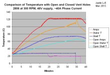
In this case, the motor took a full 30 minutes to reach 100 celcius, and doesn't look like it would have ever hit 120. After 35 minutes the power was turned off and the motor allowed to cool down. Here is the data, plotted along side model when using the exact same coefficients as the first test.

View attachment 1

Here is the actual data compared. The presence of the 3/4" vent holes reduces the motor core temperature rise by about 25-30%, and the shell temperature rise by almost 40%.

Open vs Closed Vent Test.jpg
 
adrian_sm said:
Looking forward to your results. Would be interesting if you could also monitor your controller temperatures, if you run them in current limitting/partial throttle for sustain runs.

Yes, actually I'm doing that in quite a separate set of experiments. With this particular controller having a sinusoidal output, the switching losses are 2-3 times higher than you'd get with a standard 6-step trapezoidal drive, and you get switching losses all the time, even at full throttle with no current limiting.

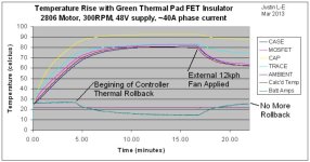
Anyways with the controller sitting in still air driving 40A of phase current (26A battery current), it hit thermal rollback at just under 5 minutes, and then the power ramped down to almost half. Once a small fan was directed at the controller enclosure, the temperatures immediately dropped, and within 5 minutes had cooled sufficiently that the controller was no longer thermally limited and delivering the full 40A/26A again. When we measured the fan air speed with an anemometer, it was only 12kph, so having the controller exposed to even the gentle airflw present when you are biking slowly makes a HUGE difference in how hot it will get. To the tune of 3 times better heat dissipation than it would have in still air or stuck in a bag etc.

Controller Temperature Rise.jpg

For the motor tests above, I had a fan on the controller the whole time so that we wouldn't have any controller overheating coming into play. However, the 3-phase FOC drive makes the direct measurement of the motor current and motor heating a bit tricky, so I think for the remainder of these tests I'm going to switch over to an Infineon device running at 100% duty cycle, and that way we can infer the phase amps as basically being the same as the battery amps.
 
I hope you have enough time to try a couple of oil fill levels, with the first one only about 100 cc's.

These are great, great tests!! Adding real quantitative and data to qualitative conjecture and observations. Nothing but good will come from this. :D
 
Justin,

Something Bluefang and I recently discovered is that without some kind of interior blades in the covers that the air spins inside a hubmotor surprisingly little, and that means very little actual flow of fresh air intake and warm air out. The 9C would be somewhat better due to the vanes in the covers, but they don't pass near the windings and are only shaped to move air axially, not toward the stator. On all of my vented motors I have included blades in the covers, and only recently understood their importance to my favorable results. Well placed and angled blades not only ensure the air spins at motor rpm, but they can also accelerate the air at the windings, creating a faster more turbulent flow at the windings.

Even at high rpm the motors Bluefang and I vented had so little flow that we could barely feel any flow. On mine, the 25t sprocket on the other side felt like it was throwing off a hurricane in comparison, and a sprocket isn't a very good fan blade. With fairly small blades inside the covers, I have always had a flow that is easily felt coming out of the exhaust holes.

Please let me know if you want any input with bladed strategies. i've done significant research and experimentation, and airflow systems design is a lot more than putting holes in a side cover.
 
the X5 on my trike got vent holes at the outer edges of the covers, reasoning was that airflow would be closest to the coils, vs closer to the middle like you have now.. Also, any water that gets in, gets flung out instead of trapped in.

I've seen methods do HUGE holes on the covers, big enough that i'd worry about breakage under load.
 
Awesome! Temperature probes tied in to limit the current when they get too hot is something I've been pushing for. Maximize power output without burning anything up. Seeing what actually helps the cooling situation with real world measurements is a great project.
 
I think this is the beginning of something big. Big enough to greatly influence manufacturers in how they go about design. I totally agree with John in CR in terms of using internal fins to increase airflow and direct it over the windings. It would be very interesting to include finned covers and axial/perimeter ventilation as one of the models to confirm the efficiency of airflow from one side to the other.

I think it'd also be good to highlight another benefit of ventilation, water drainage. Sealed motors have the dual disadvantage of an enclosed thermal space restricting performance at the least, destroying many at worst. The second, a build up of oxidisation in a sealed motor where moisture has no egress, in turn progressively reducing performance at the least, reducing longevity and seizing motors at worst.

Great work !!!
 
Excellent work Dr. Just

Cant wait to see the oil cooling results
Might be interesting to try atf fluid and mineral oil and ...

Ineresting comments in the pluses of trapezoid drive
Switching losses

Note on and an ironless halbach motor the losses are the same sinu or square
The harmonics dont matter without iron
So an ironless motor with trap drive is opt
 
So I had a bit of a setback yesterday just as I was starting the next round of tests. The constant RPM dual quadrant motor controller board that has been faithfully running the dyno for 4 years started acting up and seems to have blown one of the fet driver circuits. So it might take a couple days to get that up and running again if I have to order some parts.

In the meantime though, it means that I can start preparing the different side cover modes that we'll be using in the experiments.

John in CR said:
Please let me know if you want any input with bladed strategies. i've done significant research and experimentation, and airflow systems design is a lot more than putting holes in a side cover.
Yes, most definitely. I was going over your other threads with quite some interest. If you can sketch or draw what you think would be the ultimate fan/airflow design for the 9C style motors then give a description and we've got all the tools to fabricate it. At the moment, I'm planning to compare:

  • No Holes
  • Simple holes on one side cover
  • Simple holes on both side covers
  • Holes close to axle on one side, and near perimeter of 2nd side
  • Shaped CNC slots for much more open material
  • Vented cover with fan blades (as per your best suggestion)
  • No holes but with small amount of transformer oil
  • No holes but ~1/3rd full of transformer oil

I'm not too familiar with ATF fluids but I know that the transformer oil in addition to nice electrical properties has a very low viscosity, and so shouldn't cause too much additional drag friction inside as the motor spins. Is there a particular reason why car transmission fluids have been the liquid of choice used by most people so far?
 
ATF is thinner than many other available and affordable oils. They are designed with anti-foaming agents. ATF is widely available from synthetic stock, which means it will retain its viscosity very near its designed parameters over a wide range of temperatures (instead of thick when cold, thin when hot).

I'm not familiar with transformer oils, but they might be better in some ways. Most people have syn-ATF available off-the-shelf within a few miles of their home.
 
ATF is used for cooling in the GM Volt motor and Prius traction motors.

ATF has a number of advantages over standard transformer foil IMHO.

That's so awesome your tiny controller lasted so long! Very cool! For those who don't know, that is a 12fet sinus controller designed and made by Justin himself, and it's only a little bigger than a 6fet in size. Could be quite a bit smaller with an alternate and more local cap and TVS diode layout it bet, perhaps even the same volume of the typical 6fets we run. Just shows you how much of a badass Justin is, because for most of us that accomplishment would be like a crowning achievement, and for Justin it's like a side-note in his list of life accomplishments.

You rock my friend!

BTW- My roadbike has been running that cute motor with the uber-tiny spokes now for many stair drops and single track trails on 28mm 700C tires. :) Wheel is still holding true as can be. :) I've not yet hooked up power to the motor. :)
 
To get back on topic, I agree with John on low-hanging-fruit things that could be done to increase airflow.

The stator has tons of surface area itself to generate lots of 'grip' so to speak on the air inside, but the spinning case itself I believe could improve that internal air-turn-over rate substantially with some internal veins.

Internal veins would also improve sealed motors continuous power, as more stirring of internal air means less delta-T between stator and the outside of the case, which is ultimately what limits your Pd of a sealed motor assembly. Anything you can to do to get the outside of the motor shell hotter is how you win with a sealed motor.

With an open/drilled motor design, it seems the goal would be to simply exchange as much air volume to cross over the stator as possible to maximize cooling.

Now with your awesome test setup and willingness to take the time to find out, we will finally have more than theory and guesses. :)
 
Awsome work Justin!.. that's the kind of real test it was missing on that forum and you work well on that, Thankls for the time and efforts!

Even if you want to have some test with simple black body paint, i can help you with that, we work everyday with that kind of paing that is nearly perfect IR absorbant and emitter.

It is Called Black Velvet Coating from 3M and made by Mankiwiz. I can ship you some sinc ethe kit are 300$ for one liter but it would cost nothing since i grab the one that are expired at work for free. There is an alternative that is perfect and only have 1% diff of absorption and it is called Krylon Ultra Flat mat 1602 wich is also used for black body surface and astronomic optics and IR thermal camera shield. This Krylon can be bought at any local industrial paint shop. anc cost 5$ per spray can! I tested their absorption with our spectrometer and it is the perfect absorbant.

The idea would be to paint the inside of the side cover and also the outside . By that way the radiant heat would be captured by teh side cover instead of being reflected like aluminum does and also reemitted by the outter surface with the second ext coat of black paint.

I have always wondered how much important is the added heat of the winding due to the reflected radiant heat from the aluminum side cover. Aluminum like many other metal are very good reflector of IR over 750nm... and even the black anodized aluminum is stll reflecting 80% of the IR over 800nm ... adn up to the long wave! ( dozens of micron wavelenght! )

That paint is 97% absorbant over very large UV to long wave spectrum . We use it for the thermal camera we build for some military projects.

I really dont know how much heat the radian heat thru the side cover interface represent compared to the rest but this might certainly help.

I can send you this paint if you want to give a try.

Doc
 
That is a good idea on the inside of the motor side plates to lower the delta-T from preventing internal IR reflection.

Paint can sometimes be a surprisingly good insulator too though, it seems like if applied thin it should be all advantages on the inside side plates though.
 
Justin,

Which style of 9C covers are we talking about, the old rounded ones or the new style with square edges? If the new style I need to see a pic of the inside of the covers.

Thanks for doing this BTW. I should also give me an extra push to finish a current project and get some video using a dense smoke machine my friend has. I'm running a sealed high efficiency motor now or I'd just send some smoke through it.

My interpretation of the test so far is that the stator still gets too hot, because there's no reason for an actual intake and exhaust flow to take place. The trailing edges of those large holes create more turbulence right at the windings, and probably more spinning action overall. There may be some exchange of fresh air, but I think it must be limited.

John

PS- Don't you think 120°C is way too hot? The factory I get my motors from install a thermistor with a 95°C trip point. It is installed on the stator about 1cm from the copper, but for your continuous running that shouldn't make any difference.
 
Yes, lots of square edges. Turbulent flow. Coarse sand blast every thing that can take it, making lots of tiny square edges. Add cooling fins in thick / heavy sections that are over built or add weight weenie holes where you can. Dissipate as much heat as possible through convection. For improving Radiant heat loss, I rely on Flat Stove paint. Any number of good brands on he shelf in the local hardware store. Manifold paint is good also. Wonder if I could grind up some soap stone and add it to the paint for some added surface texture. Also possible some powdered aluminum or other appropriate metal could be added to paint for texture. Look forward to seeing the results of testing.
 
John in CR said:
Justin,
Which style of 9C covers are we talking about, the old rounded ones or the new style with square edges? If the new style I need to see a pic of the inside of the covers.
This is the old rounded style. It leaves a fair bit more room on the inside between the stator and the side plate than the newer disk motors, so will be more suited for adding internal fins.

Thanks for doing this BTW. I should also give me an extra push to finish a current project and get some video using a dense smoke machine my friend has. I'm running a sealed high efficiency motor now or I'd just send some smoke through it.
You mean running some smoke to visualize the airflow? That's not a bad idea. We have a small handheld anememoeter for quantifying flow rates but it doesn't work so well on a spinning reference frame. But if a setup has clear intake holes, then you could have large diameter pipe that fits over all of them and then measure the flow rate through that pipe to quantify how many L/min of air is getting pushed through the hub.

My interpretation of the test so far is that the stator still gets too hot, because there's no reason for an actual intake and exhaust flow to take place. The trailing edges of those large holes create more turbulence right at the windings, and probably more spinning action overall. There may be some exchange of fresh air, but I think it must be limited.
There's definitely an exchange of fresh air regardless, the interesting question is just how much this gets improved by the addition of features to force the convection much further, and that's what the finned build as per your suggestions will help us nail!

PS- Don't you think 120°C is way too hot? The factory I get my motors from install a thermistor with a 95°C trip point. It is installed on the stator about 1cm from the copper, but for your continuous running that shouldn't make any difference.

Yeah 120 degrees is not something you want to design for, but the copper windings handle it fine and doesn't risk burning the enamel. I would be nervous if the magnets got that hot, but they are thermally linked to the rotor which is a lot cooler throughout the tests.

-Justin
 
Back
Top