How is power divided between motors?

Glyn

10 W
Joined
Oct 7, 2017
Messages
70
First of all, wow, what a great resource! I’m so glad I stumbled upon it. Thanks in advance to all the admin’s and contributors.

My first post:

I’m building my daughter an off-road wheelchair which at the moment is likely going to be 6-wheel-drive. Unfortunately, my knowledge of electronics is limited, but my motivation is strong. One of the things I haven’t been able to work out by myself is this:

- - - -

Just to keep the math simple, let’s say a 100w motor will need to draw a constant of 10 amps to move a given object up a hill.

- - - -

Question 1: How is power distributed if the number of motors increases? - I realise this is a confusing question and I’m not sure how best to put this but, if two motors produce 100w each, does that mean you have 200w power, or just 2 x 100w? Is the pushing capability 200w or still just 100w?

Question 2: If one motor needs 10amps to push an object, does that mean that if I use two motors, they will then only need 5 amps each? I expect it’s not going to be as linear as this but just an overview would be great.
 
It depends on how the motors are controlled.

Let's say you push the throttle down half way.
on a speed-throttle controlled vehicle, each motor is trying to hit that set speed... say 10mph. so 1 motor will pull max amps until it eventually reaches 10mph, then the amps drop to whatever maintains 10mph. putting 2 motors on, will get you to 10mph twice as fast, but each motor pulls the same max amps. advantage is, if you set the throttle at one point, it will try go maintain this speed.

then theres a current (or torque) controlled throttle. this is more like a car throttle, where pressing it down doesnt go a specific speed, but instead puts out a perecentage of power.. hold it halfway down, and your motor will pull half its max amps. so 1 motor will pull half amps, and 2 motors will each pull half amps, giving twice the power. this has the advantage of giving you control over power output, but you have to move the throttle to keep the same speed.

finally theres dumb pwm control. this doesnt even check the current draw, it just chopps the power on and off really fast, with 50% throttle being on half the time, 100% being on nearly all the time, and 25% on a quarter of the time, etc... it works similar to the current throttle, but with no control over the power out, so if you were to aim it at a wall or too steep of a hill, it can overload and kill the motor.
 
MrDude_1 said:
on a speed-throttle controlled vehicle, each motor is trying to hit that set speed... say 10mph. so 1 motor will pull max amps until it eventually reaches 10mph, then the amps drop to whatever maintains 10mph. putting 2 motors on, will get you to 10mph twice as fast, but each motor pulls the same max amps. advantage is, if you set the throttle at one point, it will try go maintain this speed.
Ok. So say one motor needs 10amps to maintain 10mph, how many amps would 2 motors need?


then theres a current (or torque) controlled throttle. this is more like a car throttle, where pressing it down doesnt go a specific speed, but instead puts out a perecentage of power.. hold it halfway down, and your motor will pull half its max amps. so 1 motor will pull half amps, and 2 motors will each pull half amps, giving twice the power. this has the advantage of giving you control over power output, but you have to move the throttle to keep the same speed.
So if I've understood correctly, what you're saying here is that two motors pulling half amps effectively gives the same power of one motor pulling full amps?

finally theres dumb pwm control. this doesnt even check the current draw, it just chopps the power on and off really fast, with 50% throttle being on half the time, 100% being on nearly all the time, and 25% on a quarter of the time, etc... it works similar to the current throttle, but with no control over the power out, so if you were to aim it at a wall or too steep of a hill, it can overload and kill the motor.
Eek! Aiming it at steep hills and walls is my intention. I'll worry about overloading motors in the future though as I need to get a basic grasp of how things work first.
 
Just to clarify ...
1. Steering by turning front wheels ...
1 controller powering 2 motors.
... or
by adding more power to wheels on one side?
2 controllers powering 2 motors (parallel - tank style).

2.
Motor : 24V 10A = 1x speed 1x torque
Motors in series: 24V 10A / 2 motors 12V 10A per motor = .5x speed 2x torque
Motors in parallel: 24V 10A / 2 motors 24V 5A per motor = 1x speed 1x torque

Glyn said:
Question 1: How is power distributed if the number of motors increases? - I realize this is a confusing question and I’m not sure how best to put this but, if two motors produce 100w each, does that mean you have 200w power, or just 2 x 100w? Is the pushing capability 200w or still just 100w?
200w = simple answer
Glyn said:
Question 2: If one motor needs 10amps to push an object, does that mean that if I use two motors, they will then only need 5 amps each? I expect it’s not going to be as linear as this but just an overview would be great.
5 Amps each = simple answer

But!
Watts (Volts x Amps) electrical input, varies greatly vs watts (mechanical + heat) output ... varied by throttle, efficiency, rpm, load etc.
 
.
...
ebikes.ca Simulator now provides a 2 motors combined option!

I input 2 350watt motors (MY1016z3 350w gear reduction motors recommended)
2 Motor Simulation
To view output capabilities of 2 motors, each with own controller, choose ADD under Two-System Mode
 
DrkAngel said:
Just to clarify ...
1. Steering by turning front wheels ...
1 controller powering 2 motors.
... or
by adding more power to wheels on one side?
2 controllers powering 2 motors (parallel - tank style).
It will be tank style.

2.
Motor : 24V 10A = 1x speed 1x torque
Motors in series: 24V 10A / 2 motors 12V 10A per motor = .5x speed 2x torque
Motors in parallel: 24V 10A / 2 motors 24V 5A per motor = 1x speed 1x torque
That's really useful to know, thank you. Ultimately it only needs to travel at 5kph, but the gradient it will be going up will be steep in places so torque is of greater concern. However, if I've understood correctly, to have more torque requires more amps and thus a larger battery.

Ultimately what I'm worried about is not being able to find a battery that's up to the job so although the extra torque from wiring in series would be nice, in reality it will most likely need to be wired in parallel. According to my estimations (given my limited understanding) one 48v 3,000w motor will draw an average constant of 60amps to get this wheelchair up the hill (7.2km with 996m of ascent). If the estimated time to the top of the hill is 5 hours then the battery required would be...

5 x 60 = 300ah 48v battery.

And this is just for one motor, but I intend to have 6. The wheelchair then needs to get back down the hill and of course I don't want to cut it too finely. So in effect I need a 400ah 48v battery.

Now, I realise this is a very big battery, so please just humour me for a moment. Ultimately what I'm trying to understand is if I'd need just one of these batteries, or six (one for each motor).
 
You might find these other offroad wheelchair threads of interest

https://endless-sphere.com/forums/viewtopic.php?f=3&t=52659
https://endless-sphere.com/forums/viewtopic.php?f=7&t=82322

Sadly, the videos at the end of the second thread of a 4 wheel drive rig were quite amazing - but are no longer available. The woman rider did some pretty aggressive rock crawling and general off-road bashing, climbing over some huge obstacles with relative ease.

These are different approaches than what you are attempting, which sounds more like a crawler-ATV-like rig. The units discussed in the linked posts use larger spoked wheels that have little difficulty traversing fallen trees, etc. -- very different from a skid-steering crawler approach that typically has smaller unspoked wheels that can bear up under high lateral forces.

offroadWheelchair.jpg
Regarding your motor question - depending on the control mechanism you use, you will need roughly the same power regardless of the number of motors unless you are using some really lossy drive systems. An advantage of multiple motors is that the heat loss per motor is substantially reduced which makes overheating much less of an issue.
 
If you only need walking speeds up to 5mph uphill make sure you use a gear reduction that results in a maximum speed of around 10mph on flat surface.
What is your 6 wheel drive design looking like? A 4 wheel drive should be less complicated, lighter and consume less energy from a battery. A battery out of Nissan Leaf, Chevrolet Bolt or other EV modules should give you enough range to make the trip.
What kind of terrain do you want to ride with it and what weather conditions (rainy/muddy)?
Possibly a Chinese quad where you exchange the fuel engine with a very geared down electric motor would be all you need for your daughter to make the trip?
 
Thanks teklektik, those posts look great and the video of the boma7 going up the steps is inspiring.

SlowCo and for others interested, at the moment I think I'm going to go with a rocker-bogie design like the Mars Rovers but the project is at a very early experimental stage so this could change.
More info here: http://www.mountainwheelchair.com

DSC_0561.jpg
 
5kph requires gearing more than amps

Let me refer you to the Bikes.ca Calculator

Will give you a reasonable idea of requirements.
Adjust:
"grade" to required - preset 8%
"weight" - preset 330lb vehicle + occupant
etc.

Calculator
 
SlowCo said:
What kind of terrain do you want to ride with it and what weather conditions (rainy/muddy)?
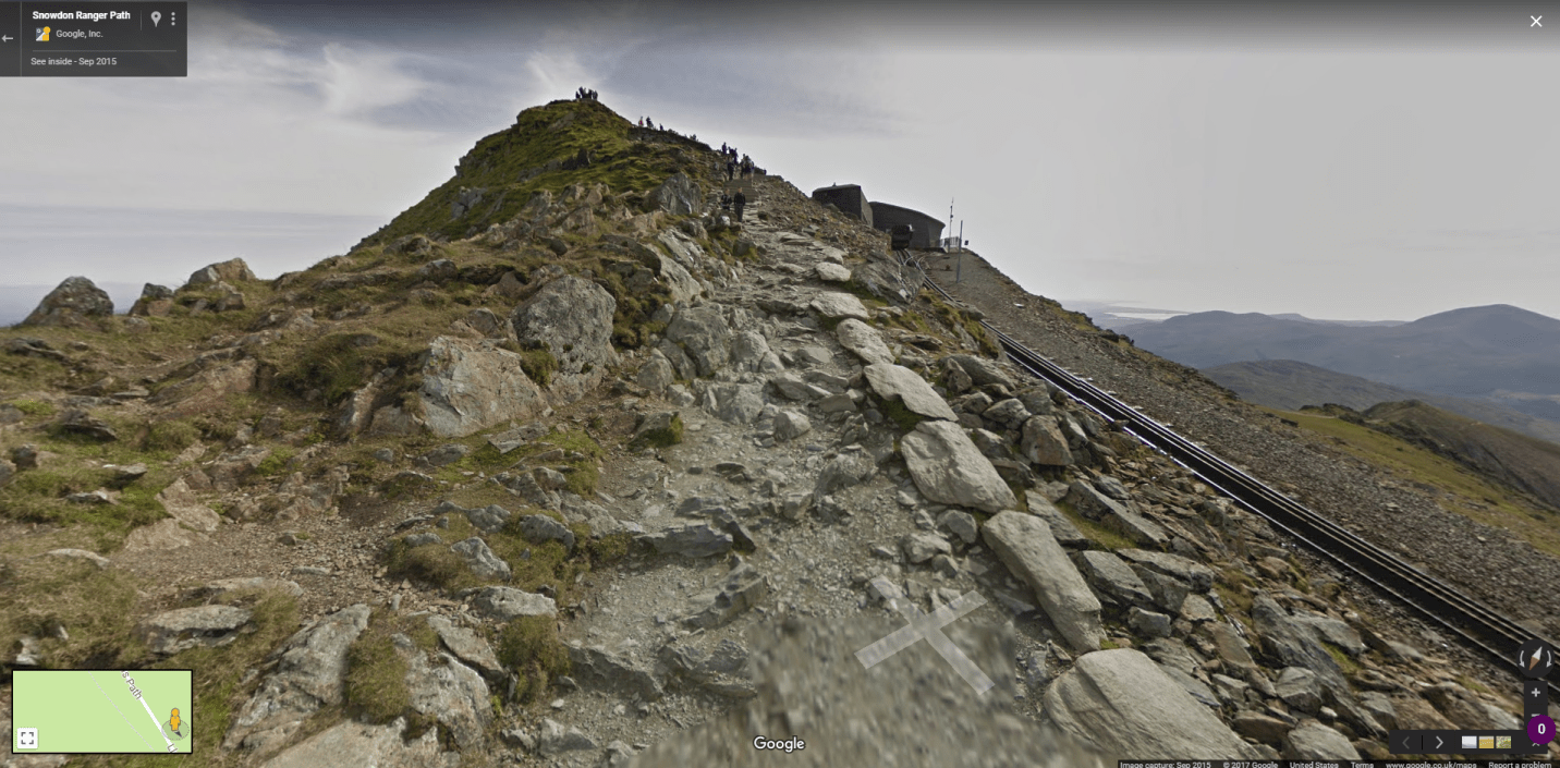
Sometimes will be used in the rain and mud but specifically, it needs to get up this path:

llanberis-path-22.png


SlowCo said:
Possibly a Chinese quad where you exchange the fuel engine with a very geared down electric motor would be all you need for your daughter to make the trip?
This was my initial thought but after looking into it, a quad would require too much upper body strength and she wouldn't make the trip. Hence I'm building something despite my lack of experience.

DrkAngel said:
5kph requires gearing more than amps
I thought that might be the case. I had intended to use motors embedded in the wheel hubs. Gearing would help calibrate torque, speed etc and get the most out of the motors. With gearing I could also potentially just use two motors (one for each side) and trasnfer power to the wheels via chain and sprockets. The only problem with this is that I like the simplicity of having motors embedded in the hubs as they're more efficient (as opposed to gears), there's less fabrication to do on my part, they take up less space when space saving is important, and I also would like to be able to cut power to individual wheels as and when required (I imagine this would be harder to do if using a geared system).
The calculator looks brilliant, I'll have to read through when I'm a little more awake.
 
If I were you, and after a motorcycle accident I gave this a lot of thought (what would I do if I had been paralyzed from the waist down), I'd only use 1 electric motor, connect it to a hydraulic pump, and use 6 hydraulic motors.

1. You could have a single motor, running at its most efficient RPM when pressure needs to be built up, pumping fluid into a small accumulator (pressure vessel).

2. You could then easily run hydraulic lines out to each of the hydraulic motors mounted on whatever kind of suspension system you want. You could then use a more traditional wishbone suspension with independent suspension for each wheel. Or even a much simpler lever arm like the trailers in this video > https://www.youtube.com/watch?v=kadg023rCJM

3. The simplicity of only 1 controller, 1 motor, 1 battery pack, actual speed and turning would be controlled by the electrohydraulic valves, or even just mechanical valves from a single joystick, or you could have 1 joystick doing speed, 1 joystick doing direction.

4. Less overall weight since hydraulic motors can be made smaller than the equivalent required electric motors. You just need to pick the hydraulic motor which has the rpm and torque capability you need. I was looking at one that was $150 and did 550rpm and 118ft-lbs of torque, continuous. That'd be around 35kph with a 14" outer diameter tire, lol. You'll probably want to keep it under 20kph, so with a 14" tire that'd be around 300rpm.

If you went all electric, you would most definitely need to use a complex system of sprockets and chains. With hydraulics, it's almost like having a hub motor, the phase wires are just 2 hydraulic lines, also hydraulic motors have the needed torque in a much smaller package. Something else I just thought up, which comes from the portal axle/4x4 world, is a hollow axle, which lets you run an air compressor system to the wheels, so you can air up and air down the tires while moving (central tire inflation system), for better traction! http://s.hswstatic.com/gif/self-inflating-tire-11.gif

Getting ahead of myself now, haha.

The only issue with hydraulics, in my opinion, is if you don't find the right motor, the sound can be a bit annoying, I road around in a hydraulic 6x6 ATV for a few months in 2015, they did not choose the right motor, it was almost worse than mosquitos flying around your head.

I would go over to Reddit, specifically to www.reddit.com/r/engineers and www.reddit.com/r/askengineers and talk to them about it if you decide to go this route.
 
teklektik said:
You might find these other offroad wheelchair threads of interest

https://endless-sphere.com/forums/viewtopic.php?f=3&t=52659
https://endless-sphere.com/forums/viewtopic.php?f=7&t=82322

Sadly, the videos at the end of the second thread of a 4 wheel drive rig were quite amazing - but are no longer available. The woman rider did some pretty aggressive rock crawling and general off-road bashing, climbing over some huge obstacles with relative ease.
Some very inspiring threads, thank you.

Yes, I think my "skid-steering crawler approach" will likely have "smaller unspoked wheels that can bear up under high lateral forces".

Regarding your motor question - depending on the control mechanism you use, you will need roughly the same power regardless of the number of motors unless you are using some really lossy drive systems. An advantage of multiple motors is that the heat loss per motor is substantially reduced which makes overheating much less of an issue.
That's good to know, thank you.
 
atarijedi said:
If I were you, and after a motorcycle accident I gave this a lot of thought (what would I do if I had been paralyzed from the waist down), I'd only use 1 electric motor, connect it to a hydraulic pump, and use 6 hydraulic motors.
Interestingly my father (retired chief engineer in the merchant navy) popped in for a visit yesterday and I showed him the project. He suggested using hydraulic motors too. Before this conversation though I didn't even know that such a thing existed.

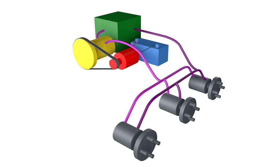
So, in my mind the system would look something like this:
hydraulic-motor.png


In this system I have one electric motor powering one hydraulic pump which then powers the three hydraulic motors on one side.
It's clear to see by looking at this it would be easy to adjust the gear ratio between the electric motor and hydraulic pump.

I imagine that I could put "electrohydraulic valves" between the pump and individual hydraulic motors and therefore control how much power each wheel receives.

What I haven't yet worked out, and would love some help with, is how I'd be able to switch between forwards and reverse on individual sides of the vehicle. Would it require two pumps? In fact, how do you switch between forwards and reverse just on one side?

atarijedi said:
You could then use a more traditional wishbone suspension with independent suspension for each wheel.
You mean something like this?
637178_mantis_6wd_main_600px.jpg

That's a possibility, but ultimately it will come down to which system I decide is more likely to get us up the intended path. At the moment I'm still leaning towards the rocker bogie mechanism but have much testing still to do.

atarijedi said:
Something else I just thought up, which comes from the portal axle/4x4 world, is a hollow axle, which lets you run an air compressor system to the wheels, so you can air up and air down the tires while moving (central tire inflation system), for better traction!
I really like this idea because even in my small RC prototype changing to softer tyres has made a huge difference. In reality though, I don't think the added weight of a compressor is justifiable.
 
.
...
A few available options ... Google search

2. I've always liked the idea of a track, on rear tires.
Cut sidewalls from heavy tread car-truck tire
deflate pair of tires
place tire tread over rear tires then inflate to secure

Be sure to leave enough sidewall to secure over sides of tires

3. Hydraulic drive has a great advantage over direct electric throttle.
Electric throttle will create a high rpm spin when traction is lost, hydraulic greatly moderates this effect.
 
Glyn said:
So, in my mind the system would look something like this:

That is pretty much it.

Glyn said:
I imagine that I could put "electrohydraulic valves" between the pump and individual hydraulic motors and therefore control how much power each wheel receives.

What I haven't yet worked out, and would love some help with, is how I'd be able to switch between forwards and reverse on individual sides of the vehicle. Would it require two pumps? In fact, how do you switch between forwards and reverse just on one side?

As you might have figured out, you need to reverse the flow of the fluid in order to reverse direction. You need what is called a "reversing valve" or "direction control valve". Essentially, it would be plumbed to change the direction of fluid for the entire side of the vehicle.

Here is how I would have the power train set up.

Battery > Controller > Motor > Pump > Accumulator(optional) > Direction Control Valve > Flow Control Valves > Hydraulic motors

The purpose of the accumulator is to act as a pressure resevoir, so you don't need to be constantly running the motor. Like the tank on air compressors for air tools.

So fluid will flow from the pump/accumulator to 2 Direction Control Valves, one for each side. Then into one of the 2 Flow Control Valves, for each side. Then into the motors.

Fwd/Rwd on the joystick would control both DCVs at the same time, Left/Right would control only 1 DCV. The amount of angle on the Joystick would control the FCVs.

Try and get motors that have as low of a flow rate as possible, and still generate the torque you would need. That will lessen any noise.

I would try and find the closest company that does fluid power sales, and talk to them about specific parts. They will have far better knowledge than me.

Glyn said:
You mean something like this?
637178_mantis_6wd_main_600px.jpg

Yeah something like that, anything really. The way you attach the wheels is probably going to be the least complex thing you design.

Glyn said:
I really like this idea because even in my small RC prototype changing to softer tyres has made a huge difference. In reality though, I don't think the added weight of a compressor is justifiable.

You can get really small air compressors. That said, you don't need to add it immediately, maybe just make the design such that it could be added in the future.

All that said, I just did a google search for a hydraulic wheelchair, and it seems someone has commercialized something similar to what you are building. It's called the HexHog, it uses 2 electric motors to power the 6 wheels, no hydraulic propulsion though, only hydraulics to push/pull the pilot chair for easier access. Looks like a cool machine, they want something like $30k though, f-that.
 
That's great, thank you :)

Ye, I've doing some research and can see how the accumulator works in unison with pressure relief valves. Have also seen directional valves used in hydraulic cylinders but I've yet to come across a true bi-directional motor. Everyone I've looked at needs tearing down, swapping around the internals and putting back together again before it will work in reverse. I am getting there though, albeit slowly :) Luckily there's a hydraulics shop about 5 minutes walk from my house!

I really like the Hex Hog, seems really well built. Unfortunately it doesn't have the ground clearance to get up the path I have in mind though and last time I looked they were asking £50,000 here in the UK (65,000 USD).
 
The only problem with having hydraulic motors is if the primary fails the wheels are not going to turn, having been up snowdon a few times its a hard walk down as it is let alone carrying a locked up machine. Have you thought about using a 6x6 base and having the motor take place of the usual small engine. the t20 transmission would give you true 6wd and a motor with a reduction gear would make it go vertical. the racing hustlers are pretty wild, i know my Max would make the path easy. the best part is you can unlock the drive to the chains and it will be easy to push.
 
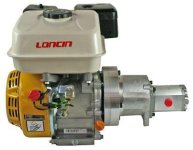
If you would go with hydraulic motors and an pump system I would choose a fuel powered pump.

16901.jpg

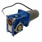
A lot of energy will be wasted using hydraulic motors so the battery would be huge to power the electric pump. If a little inefficiency isn't a problem I would just choose 6 worm drive brushed motors. You could then use a single controller to feed them. Worm drives can be found in high ratios so a correct worm drive and motor combo that results in a max. speed of 5mph should be easy to make. And a high ratio worm drive times 6 will probably result in not needing brakes.

s-l300.jpg

View attachment 1
 
Back
Top