
Der Original-Surron-Motor hat eine Hallsensorplatine. Da sind 3 Hallsensoren drauf. Sie sind um 120° voneinander beabstandet. Das einzige, was in der votol-Software angepasst werden muss, ist der Shift-Winkel! Hier sind 60°, ganz gut. Beim Selbstlernen bin ich bei 53°. Toleranz steckt also in jedem Motor. Wegen der Magnethalterung auf der Rotorwelle.Ich habe immer noch kein Glück, den Phasenwinkel eines serienmäßigen Surron-Motors zu finden. Woran erkennt man das nur, wenn man sich ein Bild ansieht?
You are using an out of date browser. It may not display this or other websites correctly.
You should upgrade or use an alternative browser.
You should upgrade or use an alternative browser.
Votol EM-100 & EM-150 controllers
- Thread starter Stefanj.
- Start date
Wattster
10 W
- Joined
- Oct 31, 2022
- Messages
- 71
Danke für die Hilfe! Das war sehr nützlich.Der Original-Surron-Motor hat eine Hallsensorplatine. Da sind 3 Hallsensoren drauf. Sie sind um 120° voneinander beabstandet. Das einzige, was in der votol-Software angepasst werden muss, ist der Shift-Winkel! Hier sind 60°, ganz gut. Beim Selbstlernen bin ich bei 53°. Toleranz steckt also in jedem Motor. Wegen der Magnethalterung auf der Rotorwelle.
8 poles, and you can confirm your motor with a compass.
 Hi again, I am not sure about the values of flux weakening. I have recorded a video of the motor spining:
By the way, self learning is not working properly. The direction doesn't change when I restart the ignition signal when the park connector is shorted. The motor spins one turn but the same direction every time. And the hall angle doesn't change when I try different vaules. Do you have any idea? Thanks in advance.
Attachments
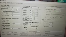
U can try disable HDC setting and try some Mid, Hi flux-weaking value. Good luck.View attachment 332112Hi again, I am not sure about the values of flux weakening. I have recorded a video of the motor spining:
By the way, self learning is not working properly. The direction doesn't change when I restart the ignition signal when the park connector is shorted. The motor spins one turn but the same direction every time. And the hall angle doesn't change when I try different vaules. Do you have any idea? Thanks in advance.
Sattva Ram
100 W
- Joined
- Jan 4, 2020
- Messages
- 271
How do i connect the 200 V2? There's no driver installation file provided. There's absolutely no way i will be able to connect without driver installation file. I put the throttle on and it doesnt spin the motor either. The LED gives off some code i guess 4 flashes but ofc there's no description of this crap anywhere. I guess it might be the throttle but if i cant connect to the PC it's useless. Seems i bought another paperweight i'm so sick of these chinese craps at this point...
Sattva Ram
100 W
- Joined
- Jan 4, 2020
- Messages
- 271
Okay i managed to connect to this piece of crap. The baudrate was the problem however it still doesnt budge. If i spin the wheel by hand the rpm meter seems to work the voltage is shown properly it accepts the parameter write too yet nothing. All votols hush and hum slightly whenever the wheel is spun manually (i mean not the votol but the motor wires) but not this one it is dead silent. Now all the throttle settings are fine too yet absolutely nothing it also gives off an LED code that doesnt seem too encoraging by the look of it one fast flash and 4 slower ones but of course there's no proper manual for this crap so who knows what it means . Guess i got a dud even if i can send it back at their expense i'll still lose 35% of its value on tax because there's no way i can get that back from these mofoz. I'm sick and tired of these industrial waste craps the Far driver is shit the votol is shit there's no good controller i'm just tired at this point i guess i give everything away to some other sucker i just dont need this ccksuck anymore. I sold my far driver on the grounds that it had issues mostly because the 72800 is a discontinued model and as soon as i heard that it's only 24 Fets and 800 phase and 430 line current an idea just came to me why it was discontinued also it didnt let you write 5 pole pairs only 4 no temp sensor and weird throttle response... so i bought this crap instead that doesnt work at all. Never knew i would cry the far driver back...should have kept that shït at least it was doing something...How do i connect the 200 V2? There's no driver installation file provided. There's absolutely no way i will be able to connect without driver installation file. I put the throttle on and it doesnt spin the motor either. The LED gives off some code i guess 4 flashes but ofc there's no description of this crap anywhere. I guess it might be the throttle but if i cant connect to the PC it's useless. Seems i bought another paperweight i'm so sick of these chinese craps at this point...
Wattster
10 W
- Joined
- Oct 31, 2022
- Messages
- 71
Hey take it easy. This thread is for users of the Votol controllers, not a place to bash and be rude.Okay i managed to connect to this piece of crap. The baudrate was the problem however it still doesnt budge. If i spin the wheel by hand the rpm meter seems to work the voltage is shown properly it accepts the parameter write too yet nothing. All votols hush and hum slightly whenever the wheel is spun manually (i mean not the votol but the motor wires) but not this one it is dead silent. Now all the throttle settings are fine too yet absolutely nothing it also gives off an LED code that doesnt seem too encoraging by the look of it one fast flash and 4 slower ones but of course there's no proper manual for this crap so who knows what it means . Guess i got a dud even if i can send it back at their expense i'll still lose 35% of its value on tax because there's no way i can get that back from these mofoz. I'm sick and tired of these industrial waste craps the Far driver is shit the votol is shit there's no good controller i'm just tired at this point i guess i give everything away to some other sucker i just dont need this ccksuck anymore. I sold my far driver on the grounds that it had issues mostly because the 72800 is a discontinued model and as soon as i heard that it's only 24 Fets and 800 phase and 430 line current an idea just came to me why it was discontinued also it didnt let you write 5 pole pairs only 4 no temp sensor and weird throttle response... so i bought this crap instead that doesnt work at all. Never knew i would cry the far driver back...should have kept that shït at least it was doing something...
There are many very helpful people here but you need to understand you bought a universal controller made by a Chinese company and there will be issues with setup and programming. It goes with the DIY territory.
Sorry but I can help you with drivers for it as after playing with microcontrollers for years I was pleasantly surprised when all the drivers were already on my computer.
Please take a minute to ask in a way that doesn't come off as a attack on Votol and you will probably get your answer.
Best of luck on your project.
Sattva Ram
100 W
- Joined
- Jan 4, 2020
- Messages
- 271
I have many votols and never had any problems with them (i mean not that couldnt be resolved) that's why i trusted it. It's not against votol more against the seller. Like why cant they hook it to a motor for 20 seconds and see if it works or not? Not saying to do it with 50 dollar controllers but with the more expensive ones at least. Should have bought from DUN store he is slightly more expensive than sia but he checks all controllers before sending it out.Hey take it easy. This thread is for users of the Votol controllers, not a place to bash and be rude.
There are many very helpful people here but you need to understand you bought a universal controller made by a Chinese company and there will be issues with setup and programming. It goes with the DIY territory.
Sorry but I can help you with drivers for it as after playing with microcontrollers for years I was pleasantly surprised when all the drivers were already on my computer.
Please take a minute to ask in a way that doesn't come off as a attack on Votol and you will probably get your answer.
Best of luck on your project.
I'm pretty sure it's dead after connecting it says controller failure and undervoltage when there is clearly no undervoltage. (Sure the controller failure likes to pop up for votols right after parameter write but it always disappears and never appears right after connecting while for this one it's on all the time)
Lemme be pi$$ed off a bit for being ripped off for 400 dodos and getting 1 dollar worth of aluminium for the price for there is no way i'll get my money back knowing what aliexpress is. And also let me warn others in the thread without being shamed.
Last edited:
Sattva Ram
100 W
- Joined
- Jan 4, 2020
- Messages
- 271
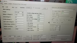
Okay it seems to be working after i fiddled with the port settings i nulled the parking brake and now it seems fine. However there's still a big problem when flux weakening kix in it spins up like absolute crazy with zero additional throttle. It just goes absolutely haywire after having reached a particular rpm and almost rips the motor apart it's very startling. HDC is set at 6200 but it well exceeds that i saw some 8000 on the display before a cut the battery wire in a hurry
Last edited:
Sattva Ram
100 W
- Joined
- Jan 4, 2020
- Messages
- 271
This controller seems like a piece of shit still. There's something seriously wrong with its rpm meter. I set some 5000 rpm HDC and it maxes out at 4000 by the display. Anyway tomorrow i'll check it with the external rpm meter...well at least now i can sell this crap to some sucker for it "kinda" worx. Maybe on load it wont be so erratic...but this spinup...i almost got a heart attack. By the sound of it it went to 15k rpm it could have even fuk up the ipm motor...I'm kinda hesitant to experiment with this controller tbh. I know that it shouldnt behave like this...anyway i think i'll hook up a 20s 1P battery on it from crap cells for testing it might prevent the spinup for it wont have amps for it with that shitpack. I got a bench supply too but that's not enough for testin...I tried different flux weakening values but all to no avail zero change....i hook up the em 50 and it worx as it should no spinup no rpm problem good flux weakening. TBH i'm tired I think i'm going for the silixcon costs what costs.
Last edited:
Sattva Ram
100 W
- Joined
- Jan 4, 2020
- Messages
- 271
Okay it seems to be working now. Tbh i have zero idea why it went haywire with the setup it came with. The problem might have been with the 3 speed....frikkin mystery...i'm using the setup it came with except i put the 3 speed to button so it accepts the default speed and it worx now...(who knows tho if it worx properly on load alas i cant try it out now...)
The sport mode switch doesnt seem to work tho. Not that it matters as the three speed is by the sport mode anyway so "hige" is sport anyway. I'll check later if the butten switch worx...
The problem might have been with the current loop settings....As in middle mode it's utterly different than in hige. There's still some mystery to this controller....I tried to write the same "flux weakening" (or rather KP values) in middle mode as what was in high basically making middle the same as high (some 12k and 6k) and it spun up but couldnt hold the rpm and wound down and also stopped working and needed a restart. So it seems to me that there is fundamental differences between the modes even if you make all values identical it wont work....
Wattster
10 W
- Joined
- Oct 31, 2022
- Messages
- 71
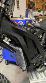
Em150 on a Surron. Build log here, Surron controller upgrade
Attachments
Just curious: Why not just change the gearing a bit to get the necessary RPM?
Rather than spending all the money for changing out the battery to a higher voltage pack, and risking blowing up the controller either directly from the overvoltage (assuming literally only 100v, and not a 100v pack that would actually be closer to 120v full) which is more than 10% over max limit according to QSmotor's site 100A VOTOL Controller EM-100 for Hub Motor and Mid Drive Motor "Voltage: 48V-72V (max. 90V)." or from the inevitable voltage spikes that happen during operation, power up, and shutdown.
Rather than spending all the money for changing out the battery to a higher voltage pack, and risking blowing up the controller either directly from the overvoltage (assuming literally only 100v, and not a 100v pack that would actually be closer to 120v full) which is more than 10% over max limit according to QSmotor's site 100A VOTOL Controller EM-100 for Hub Motor and Mid Drive Motor "Voltage: 48V-72V (max. 90V)." or from the inevitable voltage spikes that happen during operation, power up, and shutdown.
You can connect all the phase wires color to color, and the halls color to color, all matching. With wheel offground, slowly increase throttle, while watching battery amps on your wattmeter, ammeter, etc.
If the wheel spins the right direction, and current is very low (less than an amp or two, typically), you can keep increasing throttle until you eventually reach max, as long as no problems occur and current does not keep going up much (a few amps at most, say 3-5), and that means you probably have the right phase/hall combo there, but you then have to do the same test while riding. (current will be higher, but should increase fairly linearly from slow to fast if riding on a flat road with no winds, depending on your max intended speed).
If any unusual or unexpected noises occur at any stage of any test, stop the test.
If motor is spinning the wrong way, swap any two phase wires and retest.
If current increases above expected, stop the test.
If you don't stop the test when you get unexpected results, you can damage the controller (blowing up FETs, usually). This is why you need to monitor battery current, and increase throttle slowly, so you have indications of problems before they break things.
If it isn't working as expected, leave phase wires as they are, and swap any two hall wires. Keep track of which wire color combinations you have already tested, and the exact results you got, to eliminate combinations.
Repeat the tests until it does work as expected, referring to your notes so you don't repeat combinations already tested.
If none of the hall combinations work, then go back to the first hall combo and swap any two phase wires, and retest until it works as expected (again, noting combinations and results).
It normally shouldn't take more than six tries to get the right combo--even though there are 36 possible combinations, AFAICR 5 of the six sets of six are just "rotated" around by one wire color pair, and so are actually the same as the remaining set of six.
There are other threads and posts describing this test in various ways, including some with charts you can check off if necessary.
Yes, that is what the test procedure does--it finds the correct phase/hall combination to operate the motor without excessive current draw (which causes motor overheating).
Another cause of motor overheating is a motor insufficient to handle the load placed on it, or incorrect gearing between motor and ground for the speed it's run at vs the terrain/load. Or insufficient cooling (such as having an enclosure around the motor, etc).
If the controller has an actual angle setting for the halls, you can check with the motor manufacturer to see what they installed them at, but it is normally 120. 60 degree halls are not very common.
Why they call it a "hall angle" test I don't know, because it isn't determining hall angle, it's determining the proper hall/phase combination (in other controllers they usually call it "self learn", but Kelly started calling it "hall angle identify" and that infected other companies' documentation....
You could in theory have a motor with advanced or retarded timing (non-neutral placement of sensors, so they run differently in forward than in reverse, requiring special controllers with settings to compensate for this to operate correctly, but these are rare.)
If you have to actually find this angle manually, you'll probably need an oscilloscope to compare the hall signal output vs phase signal input; they typically line up, so the amount of timing difference could be converted to degrees, knowing how many degrees each magnet takes up around the rotor, vs how many changes are made in one phase cycle, etc. (sorry, I don't know how to express the math for it). There are some motor controller design threads with scope pics that show the typical timing you should see.
Last edited:
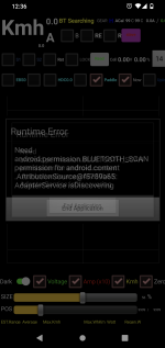
It say android refuse agree share your BT for APP. I'll update a App version to ask BT dialog.Fishblood, any idea why I get this error on your app when Bluetooth is turned on? Does it on my phone and tablet. Thanks

Last edited:
Wattster
10 W
- Joined
- Oct 31, 2022
- Messages
- 71
Thanks, believe I have the hall and phase order correct. Same motor and gearing as before but the motor no runs hotter. Had one guy say he did a hall angle test with a Votol that would and ended up at 53°. The magnetic ring is just pressed on the motor shaft to can see how there will be a variation. I was thinking about a oscilloscope to try and plot the shift but just have a ghetto single channel. Backed it off to 55° and no difference in sound but runs cooler.Yes, that is what the test procedure does--it finds the correct phase/hall combination to operate the motor without excessive current draw (which causes motor overheating).
Another cause of motor overheating is a motor insufficient to handle the load placed on it, or incorrect gearing between motor and ground for the speed it's run at vs the terrain/load. Or insufficient cooling (such as having an enclosure around the motor, etc).
If the controller has an actual angle setting for the halls, you can check with the motor manufacturer to see what they installed them at, but it is normally 120. 60 degree halls are not very common.
Why they call it a "hall angle" test I don't know, because it isn't determining hall angle, it's determining the proper hall/phase combination (in other controllers they usually call it "self learn", but Kelly started calling it "hall angle identify" and that infected other companies' documentation....
You could in theory have a motor with advanced or retarded timing (non-neutral placement of sensors, so they run differently in forward than in reverse, requiring special controllers with settings to compensate for this to operate correctly, but these are rare.)
If you have to actually find this angle manually, you'll probably need an oscilloscope to compare the hall signal output vs phase signal input; they typically line up, so the amount of timing difference could be converted to degrees, knowing how many degrees each magnet takes up around the rotor, vs how many changes are made in one phase cycle, etc. (sorry, I don't know how to express the math for it). There are some motor controller design threads with scope pics that show the typical timing you should see.
Will keep reading and see if there is some trick to be learned, thanks for the help
Same controller, too? Different controller = chance of different design, wiring, etc.Thanks, believe I have the hall and phase order correct. Same motor and gearing as before but the motor no runs hotter.
If new controller has higher current limits, then it allows higher power to the motor for loads high enough to draw it, which also heats the motor more, especially if gearing is not correct for that load. (in this event, it wouldn't have heated up before because of the lower current limit of the previous controller).
Some thoughts and general motor information below:Had one guy say he did a hall angle test with a Votol that would and ended up at 53°. The magnetic ring is just pressed on the motor shaft to can see how there will be a variation. I was thinking about a oscilloscope to try and plot the shift but just have a ghetto single channel. Backed it off to 55° and no difference in sound but runs cooler.
Magnetic ring? Do you mean the rotor, with the magnets that operate the motor, or a specific encoder ring?
If it's a specific encoder-only magnet ring, then there are multiple types of output that a sensor reading such a ring could have. The most common is SIN/COS, not UVW; if interested you can look up the other encoder types. If it is not a UVW encoder, like standard halls that read the rotor magnets, then the hall/phase order doesn't exist, because it doesn't operate that way. The hall/phase order only applies to UVW hall sensors, where there is one sensor for each phase; if it's not a UVW encoder, then most controllers can't read it and won't operate the motor correctly if at all, unless they are sensorless-capable, because they
It could still be a UVW encoder, where they have magnetized the ring as a series of opposing-polarity strips, with three hall sensors placed at either 60 or 120 electrical degrees around the circle, (or some other angle, though that angle would be the same for all motors of that design, so the manufacturer could tell you exactly what it is--it should in fact be in the motor specifications).
In this event, if the ring is correctly installed, it should always be at the same relative rotation angle as the rotor magnets, aligned with them. If it is not, but instead is either intentionally installed offset or just randomly installed at the factory because they dont' care, but the hall sensors that read it *are* always at the same install point (bolted to the motor frame, etc), that's where an "angle" could come in, which is advance or retard angle, the number of degrees positive or negative from centered / aligned with the rotor magnets.
If the offset is intentional, then the motor manufacturer can tell you what the angle is, and again it should be part of the general motor specifications available from them, because it would be the same on every motor.
If it's random because they don't care how it's installed, then it is up to the user to figure out on every single motor they have what each motor's offset (retard/advance) angle is. This sounds like where you are at.
Quinc
1 kW
- Joined
- Apr 18, 2016
- Messages
- 341
She handles way over the adveritsed amps so maybe it will handle the extra volts too.Just curious: Why not just change the gearing a bit to get the necessary RPM?
Rather than spending all the money for changing out the battery to a higher voltage pack, and risking blowing up the controller either directly from the overvoltage (assuming literally only 100v, and not a 100v pack that would actually be closer to 120v full) which is more than 10% over max limit according to QSmotor's site 100A VOTOL Controller EM-100 for Hub Motor and Mid Drive Motor "Voltage: 48V-72V (max. 90V)." or from the inevitable voltage spikes that happen during operation, power up, and shutdown.
") I haven't made a new video yet but dropped the sprocket/chain and went direct with couplers. Picked up a couple b-max packs from jag35. Full charge is 100.8v. Guess I will need to get the hacksaw out and drop her down to 22s.
I haven't made a new video yet but dropped the sprocket/chain and went direct with couplers. Picked up a couple b-max packs from jag35. Full charge is 100.8v. Guess I will need to get the hacksaw out and drop her down to 22s. EM-150 shutting off when battery reaches 80%
Hello, I was posting about my E-Motorbike build a while back but disappeared for a while as I built my battery. The battery is complete and generates about 150amps peak and 120 continuous. I have a smart BMS that shows me the condition of the battery and every thing is fine, at 80% each LifePo4 cell is at about 3.2v in a 24s 72V battery. However, at this point the controller starts shutting off. Can anyone point me to a possible issue I can research to learn about what's going on?
At first it can handle all the power the battery can give pushing well up over 100 amps, the battery is reporting over 6Kw of power. but down around 80% it starts tripping the controller and i have to cycle the power to get it back on. Then it does it more and more at lower power consumption until it shuts off and wont come back on until i charge it.
I set current limiting to 200 just in case and over and under voltage to 60 - 88. This is just to leave the battery management to my BMS. I dont want the controller doing any of that. What could the controller be feeling that causes it to shut off when the bms is still reporting plenty of voltage?
Thank you!
Similar threads
- Replies
- 13
- Views
- 3,845
- Replies
- 13
- Views
- 9,293