Is there a good rule of thumb on max phase amps given a motor's known KW and Volts?
There is no rule of thumbs.
You start with a low number of phase current and then you raise it until you think it is enough or the motor starts heating very fast.
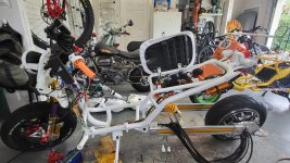
Before I had installed in my 190kg scooter with 7,7kwh batttery a QS260 60V5000W Motor running at 77V nominal voltage.
With the ND72680 set to 280bA and 630pA I could heat the motor in three runs from 0-100kph to 130C. During normal driving it only sometimes reached 140C where the controller starts to reduce power. I think this motor was maxed out in my heavy scooter.
The new QS10kW sees 400bA and 1400pA and it doesn't heat up as fast as the old 5kW Motor. I think this one could be feed with a little more power.
The old motor had 13mm² phase wires the new has 25mm² phase wires.
Yours has 2x20mm² phase wires, which will be capable of even more phase amps for short burst.
I would start with 1300pA and drive and see if it is accelerating fast enough for you, if not raise it to 1500pA and look if it heats to fast, if not ad another 100pA.
Heating of the motor depends on how long you apply high currents. Basic calculation for heating is I²xTime .
So 500A for 10 seconds will produce the same amount of heat in the motor as 1000A for 2.5 seconds.
But you only need high phase currents for acceleration and only at lower revs.
They sell your motor also with the ND962600 Controller.
The nominal phase current should be written in the datasheet from the manufacturer, but that current ist at nominal power at high revs for 24hours. That current will be around 200A.


")