DIY Pulse Arc welding copper directly to cells

devmonkey

100 mW
Joined
Aug 15, 2020
Messages
42
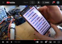
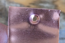
I have been working on a completely DIY TIG pulse arc welder for direct welding of heavy copper to high discharge cells, I made a short video of some test welds of 0.3mm copper onto 0.2mm steel, works completely differently to a spot welder, needs tiny power in comparison and generates almost no heat, check it out:

It has taken many iterations of the electronics, mechanics and software and 10s of thousands of test welds to get it to this point.

The welder can also weld nickel and nickel copper sandwich to cells. It will function as a precision micro welder for other tasks like jewellery or welding dissimilar metals for thermocouples, terminating copper hairpin motor windings, etc, and probably a lot of tasks a laser micro welder would be used for.

It would be simple to attach the weld head to a cnc machine, e.g. a 3d printer or cnc router, to allow for semi automatic pack assembly.

Commercial units capable of pulse-arc battery welding start at $30k, I haven't decided whether to try and turn this into a product aimed at the hobbyist market, or to open source all or part of the system, but I will post further progress here and answer what questions I can.
 
Looks great! I'm going to ask the first question, then. Being an arc welder, it means that your electrode doesn't touch the material, right? When you place it on the strip, only the cup makes contact, and the electrode is suspended over the material. Did I get this right?

Are you using regular TIG electrodes or something special for this? Could this run off of a regular TIG welder too assuming it has a tack (impulse) mode?
 
The electrode starts in contact with the workpiece and is lifted off mechanically, the current and electrode distance are tracked 100,000 times per second and the current former controlled (i.e. the current is adjusted closed loop at 100kHz) to ensure the arc forms cleanly. The electrode pressure on the workpiece, warmup time, etc are all process parameters.

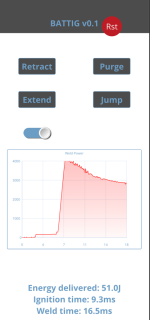
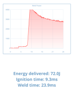
Once the electrode is the configured distance from the workpiece the arc current is ramped up and the full weld profile (with whatever agitation profile has been configured) is executed. The instantaneous energy rate (power) is calculated in real time and integrated, the weld terminates once the configured energy has been delivered.

You cannot control the arc formation or energy delivery with a normal TIG welder since it is not designed for this. A normal TIG welder uses a PWM inverter to generate the weld current which isn't suitable for very narrow precise control and pulse shaping and requires an inductor which introduces lag and non-linearity and danger. TIG tack welders usually have a resolution of 100ms in the time domain and no energy domain control and the HF start makes it impossible to accurately position the weld. I actually spent a few months last year messing around with my TIG welder trying to do this before determining that those machines not only do not expose the process parameters we need but more importantly their internal current formers are unsuitable/unmodifiable for this process which needs to complete in a few milliseconds.

The welder presented here uses a pure DC current former.

I have been using normal tungsten. With the weld profiles tuned correctly the electrode almost doesn't wear at all and is never contaminated.
 
Last edited:
Well, looks great for DIY enthusiasts, but maybe it could be even developed into a commercial product? So many possible uses, different materials, looks so easy to use and get repeatable and precise results...
 
BTW how do you track the distance and do current measurements with such high update frequency?
 
Nice work and very interesting!

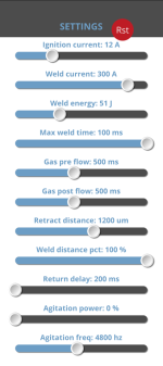
I captured this screenshot from your video, one parameter is Gas pre flow and Gas post flow.

1. What type of gas and why is it needed?

2. What's the outside diameter of the copper cup tip?

3. Have you done test welds on "high discharge cells".

Screenshot 2025-03-17 at 9.55.49 AM.png
 
Argon is needed as a shielding gas, required as per any InertGas (the 'IG' in TIG/MIG) process. Reduces the voltage required to Ionise the gas to make the arc, causes the arc to be much more stable than if struck in air, and stops workpiece and electrode oxidising. Doesn't use very much you can use a $10 disposable bottle for a few thousand welds. Part of the process is control a gas valve to flood argon around the electrode, those are the settings you refer to in the video.

Cup is ~8-9mm OD, not really critical as long as there is decent clearance to the electrode. On this version of the weld head I've using the cup to ground the workpiece, in previous versions I used a separate crocodile clip connection to the workpiece. The cup method is a bit quicker to use.

I've welded lots of old cells to check the process, I'm currently building some JP40/AM04 high powered packs.

I really need to fully discharge a few welded cells and cut them apart to check the internal damage at different weld settings, I've done this before when I used to spot weld large packs with a new type of cell in order to fine tune the settings, I hate doing it which is why I am putting it off, and I haven't done it with a tabless cell before.

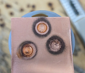
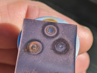
On my simple steel blade tests the reverse side damage is far less that what is caused with a normal spot welder using the nickel/copper sandwich method in order to achieve the same 'nugget' size, so I don't envisage any problems.
 
Last edited:
This is amazing work. I think one of the biggest downsides of resistance welding is the unknown effects on the cell internals of the weld on the negative end of the cell. If this is welding significantly faster with less energy input, in theory, it should be able to be tuned to reduce cell damage. This is probably really hard to quantify, but perhaps you could just do some test welds on steel of similar thickness to a cell can and view the changes in color of the back side of the weld compared to spot welding.
 
This is amazing work. I think one of the biggest downsides of resistance welding is the unknown effects on the cell internals of the weld on the negative end of the cell. If this is welding significantly faster with less energy input, in theory, it should be able to be tuned to reduce cell damage. This is probably really hard to quantify, but perhaps you could just do some test welds on steel of similar thickness to a cell can and view the changes in color of the back side of the weld compared to spot welding.
Thanks!
Yes I edited my post above and think we cross posted about cell damage. The steel blades I showed in the test and very thin, normal blades are 0.5mm, these are 0.2mm (super cheap) and as thin or thinner than any cell I've cut open. But as I said I will get around to cutting open a few JP40/AM04 cells after welding to see what it looks like, it is just a horrible job as you are never sure what might happen chemically despite fully discharging to zero volts first.

On the question of less energy input this maybe missleading, although it is much more precisely controlled than with a spot welder. The energy in this welder is monitored directly around the arc itself, it is reporting the energy it has poured into the arc which is all (100%) turned into extreme heat. A spot welder dumps energy into cables that have resistance, and has to flow current through all the layers of the weld down to the interface. The actual energy used to melt the metal at the interface is probably similar to this pulse arc method but the whole process is only say 5% efficient, whereas this is more like 50-60% (the current former is only 50% efficient). Since this welder can observe 100% of the energy that is being used to generate useful heat it can be much more precise.
 
Last edited:
That's pretty cool. I made a really crude pulse arc welder from the high voltage starter from a xenon lamp ballast and a 250v capacitor. It worked, but lacked any agitation and didn't make very good welds.

What do you use to move the electrode?
 
Have you test welded copper to copper, copper to aluminum? What stage in development are you at and where to you plan to take it?

edit: I hope you make a DIY kit available, if feasible.
 
Last edited:
Have you test welded copper to copper, copper to aluminum? What stage in development are you at and where to you plan to take it?

edit: I hope you make a DIY kit available, if feasible.

Copper/Copper works, I haven't tried aluminium, do you mean thin aluminium (like the copper) or just a piece of bar?
 
Copper/Copper test was just 0.3 to 0.3mm. I just tried 0.3 copper to 3mm aluminium, doesn't work as the massive aluminium sinks all the heat away. I don't have any thin aluminium to test unless you can think of something I might have laying about?
 
Copper to aluminium foil works, foil was doubled over until about 0.3mm thick, not sure if this is a valid proxy for an aluminium cell wall.
PXL_20250317_184526810.jpg
 
Probably I didn't change the power.

I just welded 0.1mm copper to 0.08mm aluminium soda can at 2J energy. Worked ok but the material has no strength. I think if you wanted to weld to a thin aluminium cell wall you would want to weld using aluminium bus bars rather than copper. Copper has a much higher melting point than alu so there will always be a high chance of burning through.

Tack welding thicker alu together is simple with a normal TIG so no reason it wouldn't work with this.
 
I really need to fully discharge a few welded cells and cut them apart to check the internal damage at different weld settings, I've done this before when I used to spot weld large packs with a new type of cell in order to fine tune the settings, I hate doing it which is why I am putting it off, and I haven't done it with a tabless cell before.

On my simple steel blade tests the reverse side damage is far less that what is caused with a normal spot welder using the nickel/copper sandwich method in order to achieve the same 'nugget' size, so I don't envisage any problems.
Something to consider…
While damage can occur to the central internal weld pointon the bottom of a cell (if we try to weld there externally) another, possibly larger, concern is that the cell’s electrolyte starts decomposing at about 80°C… a temp easily reached. No visible damage to the inside of the bottom of a cell is needed to create decomposition byproducts that reduce capacity and increase internal resistance.

Can this be an avoided? Not really, at least not with any affordable DIY setup. But we can certainly make it a priority to minimize heating and realize that if we see even the tiniest bit of heat markings on the inside of a cell we’ve gone far, far beyond the temp needed to decompose electrolyte.

I love this project and think it’s a great step forward towards reducing heat (which will extend the life of a pack). I only brought all this up because I feel the communities aren’t realizing how sensitive a cell is to heat damage. Everyone just concentrates on avoiding the center and obvious heating signs (color changes) elsewhere. That’s not enough IMO.

Well, not enough if we claim that pack life is a concern. 🙂
 
Last edited:
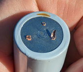
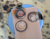
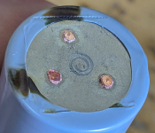
Some test welds to a JP40/AM04 at 50J, ~16ms for the weld, fused area are approximately 2mm^2 per weld so 3 welds per cell should be enough, equivalent to 10awg. Arc flash singed the shrink wrap brown on the edge weld.
1742289406380.png1742289436126.png1742289454361.png1742289492079.png1742289688753.png1742289752631.png
 
Back
Top