• Hello ES! We could use some help to get us past the finish line on building the new knowledgebase for the forum.
    Can you donate? Please see our fundraising page. Thank you!

Eahora M1PS Knight Restoration

Quick little test run:


At max, 824 rpm, that's about 46mph. Didn't even get into field weakening, which I clearly have set *way* too high (I think it's set to start around 1000rpm). That said, I probably let off the throttle a bit early for it to switch into FW mode (you can see it stays in MTPA the entire time) but, I mean, it's not a drag strip.

Max phase amps I could see was 312; but there was a pretty big delay at the start from 0 -> 312, so I fully believe while it was in the earliest RPM's it probably hit the full 405A max configured. By about the 10 second mark the battery and phase amps have equalized.

I'll have to get this fully charged and take it up some hills and do some longer pulls. I also want to find a better way to sync the screen and video. (Oddly, the stock charger only takes the battery up to 83.7v -- quite a bit shy of the 84.4 it should be, but maybe the charger needs a potentiometer adjustment, or it's just set to extend battery life.)
 
Last edited:
Sorry, to clarify: that’s the voltage at the charger output, battery has no chance to get to “full”.

To be fair — the loss of <1v at the top probably doesn’t do anything meaningful.
 
Ah, ok.

FWIW, if it's a 20s typical li-ion battery, 83.7 / 20 is 4.185v. Certain cells (like the EIG NMC I have) don't charge that high, and only go to 4.15v, or other less-than-4.2v levels. So dependign on the specific cells used, it might use that lower voltage charger for safety.

The charger itself in your pic shows 84.0v on the label, so best guess is that it isn't the above, it's just a tad low on the output, misadjusted, etc.

If it was 84.4v, that'd charge 20s to 4.22v/cell, which is probably an overcharge for most cells.
 
I believe the company claims them to be some spec of samsung cells; so likely a regular set of 4.2 bunches.

And, yeah, 84.4 is a tad high -- I don't honestly know where I pulled that number from...

Did a little hill climb; roughly a 10% grade and then did a full speed run; got into the field weakening control zone as well.

Top speed was 55mph with the battery at a 77v resting voltage, it sagged to 70v to get that speed.


Motor never went over 70C -- there's a lot of headroom on this motor now for more power, but the battery is likely at it's limit, and even then, the controller is only good up to 150 battery amps, so I don't think there's a lot more room there anyway. I believe this bike could hit freeway capable, but you'd need to upgrade to 96v to get there. Not sure I'm interested in that -- a more capable 72v battery and controller combo might be a better setup.
 
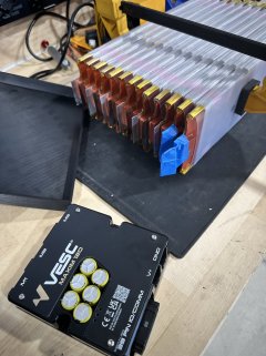
There's very little information about what the battery is on this bike, so I wanted to get into the nitty gritty and see if their claims of a well built, high quality cell stack up.

tl;dr: Yeah, very well made. 80A max, 20s8p Samsung 50E cells with good build quality.

What I found inside are, as best I can tell, Samsung 50E (v2) battery cells. Basically these: Samsung 50E 21700 5000mAh 9.8A Battery

And, as tested here: Bench Test Results: Samsung 50E (with a “2” on the wrap) - 9.8A 4900mAh 21700

The battery is well constructed with sufficient nickle coverage, a BMS that's rated for the expected load, and an internal (though soldered on) fuse. The nickle coverage is good for 80A, the bms is rated for 80A, and the internal fuse is 80A.

The pack is well taped up, well protected, and basically ticks every box for a solid, well-built battery in my book.

While I have been running this pack at 100A for the last few days, I'm going to turn that back down -- these cells can burst up to 15 amps, and surprisingly nothing in this chain of "80A only" devices and fuses has triggered, it's still not a good idea to push these that extra little bit.

I did a video of the deconstruction as well:

 
I removed the passenger seat -- none of my passengers liked it, and I hated how it was always smacking me in the back.

Due to the fact that it's hooked on to the swing arm, when we hit bumps passengers felt like they were being catapulted forward. The spring suspension on there is a nice idea, but it's not adjustable at all and the springs are too heavy, so they really don't do much.

As for me, because of the location of the pivot point on the swing arm, where the driver seat is, and the elevated passenger seat, the whole thing would compress into a V shape on suspension load up, which causes the seat to smack the driver in the back.

So, not a fan of the design, passengers not a fan of the ride. Bummer!
 
Last edited:
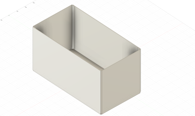
Ooff. Making a box for this is going to be more complicated than expected. It's just barely too large for my printer -- and that's with next to no allowance, and I'm sure I'd need some.

I can, in theory, slice up the box into many smaller pieces, but recombining them back into one is a gluey, structurally-dubious mess. Plus, it's really hard to split the box up into interlocking parts that can be rejoined cleanly. No slicing software does a good job of that.

I also explored making a sheetmetal box and riveting it together:

Screenshot 2025-10-21 at 10.02.16 PM.png

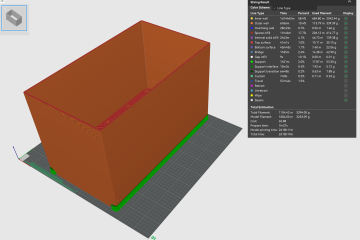
Which seemed pretty promising, alas sendcutsend said they can't/won't bend up a shape like this because it's too large :/ But, also, if I make any mistakes in the sizing for the sheetmetal, I'm out some $$$ to have it redone, and on their timeline.

I did measure it, and everything I want to do is < 500mm, so in theory...

Screenshot 2025-10-21 at 10.03.43 PM.png
I could just print this entire box in one go with a 500mm3 printer.

If only something like that existed...

That would allow me to try again, at just the cost of materials. But it's also ENORMOUS and I'd have to find somewhere to put it, but also justify having it beyond this one project.

I'm about thiiiiis close to a bunch of 3/4" ply and pocket holes.
 
That shape is so simple, if you really want it out of solid plastic you can just buy some really thick sheets of opaque extruded acrylic and use a plastic solvent like Weld-On 3 to join any edges you can't produce by bending.

I use something similar with 60cm x 90cm 3mm clear acrylic sheets cut into fancier shapes on the huge Epilog laser at work to make a lot of my stacking tool drawers and part picker bins:

That said, a steel army surplus ammo box would be way safer in the case of fires.
 
The battery plan, so far:

For protecting the bolts, I've seen someone on ES use lengths of PVC tubing. I think that would work very well and might be less cumbersome than extra plates. Following this with interest, I am so swamped under other stuff I barely made any progress with my battery.
 
For protecting the bolts, I've seen someone on ES use lengths of PVC tubing. I think that would work very well and might be less cumbersome than extra plates.
Yeah, that could totally work. The sheets, though, are just thin ABS sheets I can pick up locally and cut to size with scissors -- nothing too involved. Plus I can then secure them in place to the side of the batteries. Compared to trying to line up a bolt, sleeve, plate, and get it all inserted, especially for the middle bolts, I think it'll pan out a lot easier to work on.
 
Measure twice, cut once bites again!

IMG_4293.HEIC_compressed.JPEG

That black plate is only supposed to be about as wide as the right-most pole. I modeled the cells completely wrong. I used the full width as the width without the tabs; then added the tabs on top of that. Dern it!

I also found that the website lists these as 1/2" (12.7mm) in thickness -- not even close. My tape shows at least 5/8" and when I stack a bunch up together (to account for them not being perfectly flat; they bulge every so slightly in the middle) the better nominal thickness is 17mm. WAY different when you're stacking 13 of them up.

Fortunately, the black sheet is just HDPE, so I can just trim it down and, luckily, it leaves 4 connection poles in a pretty good spot. As for the thickness mis-measure, I haven't started on the box yet so I'll be fine on adjust that to reality once I get there.

Woof!
 
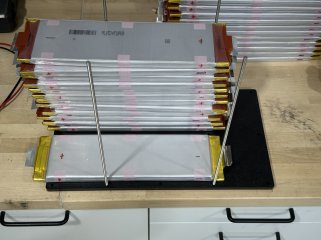
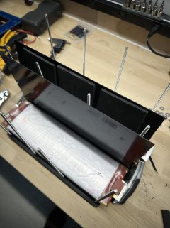
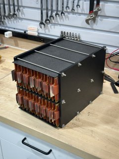
Trimmed the plates down (lucky it worked out so well), picked up the threaded rod, cut up some foam for the interior padding and got it all bolted together. Getting 12 holes to line up was...tricky. Ended up kinda tilting it up on one edge so I could insert one row at a time, lightly add the nuts, then move to the next row. Came together pretty nicely.

IMG_4304.HEIC_compressed.JPEG
(Interior plates and padding splayed out while the cells get stacked up)

IMG_4305.HEIC_compressed.JPEG

I also figured out that the red "blocks" of rubber near the tabs are just held on with some pliable double sided tape. It might become necessary to remove those so the fold-over-bolt-through connection method has enough room behind the fold for the inserted nuts. I only removed one just to verify it, will see if I need to do the rest or not.

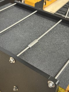
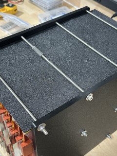
I'll keep searching around for 250mm bolts, not threaded rod. I'm not happy with how each rod ends up at a different depth. It's just hard to control which side's nut spins while wrenching. There is also a little bit of warping in the plastic on the ends since they aren't technically over the solid part of the cells. If I were to remake these plates, I'd shrink them up even a little bit more -- maybe make them out of metal with a separating piece of plastic/fiberboard/whatever for isolation. For now, this setup will do.

Also, damn this thing is HEAVY. Spec sheet says each cell is 3lbs, so that puts it at 78lbs for just the cells. Once it's got a case, wiring, bms, etc all wrapping it up I expect it to be shy of 90lbs or so.

Time to look into slightly better shocks for the bike, lol.
 
> It's just hard to control which side's nut spins while wrenching

Could always double up the nuts on one side to make a lock nut by tightening them into each other. It's pretty common with threaded rod to just grind a slot in the end and turn it with a flat screw driver too, though. The most basic form of grub screw, basically. Not rare to just grind a pair of wrench flats into threaded rod either.
 
Could always double up the nuts on one side to make a lock nut by tightening them into each other.
Ah, that gave me an idea.

IMG_4313.HEIC_compressed.JPEGIMG_4312.HEIC_compressed.JPEG

I have some couplers laying around. The extra nut to locknut that is just to keep the half-and-half depth roughly even. Bit more hardware than another approach, but will be perfectly "even" on both sides.
 
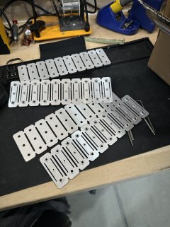
Got the connector plates today!

IMG_4331.HEIC_compressed.JPEG

These come from sendcutsend with the press-fit threads added (m5 on the edges, m3 in the middle because of tolerance requirements). Just ran them through the band saw to separate them out. (SCS wouldn't cut them out individually -- some kind of "part too small" requirement.)

Not too big a deal, but does leave a small bur that I'll need to come back and smooth out with a jig and flush-trim router bit.

In the mean time, I took one of the "smoother" ones and gave it a go.

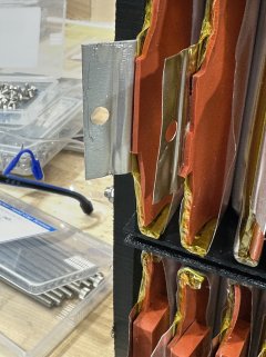
I do, in fact, plan on cutting off all the little rubber blocks and trimming them back a bit. This way the tabs are fully laying over each other. While I can teeeechnically make them reach without doing that, it's only about 1mm of overlap and that's laaaame.

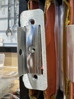
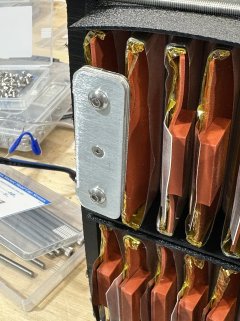
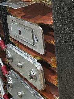
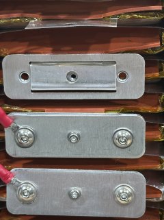
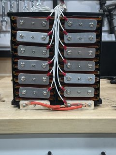
Punched holes (with a regular'ol hole punch) for the center pass through, added the back tab, sandwiched the top plate and bolted it together. Feels pretty good to me.

IMG_4332.HEIC_compressed.JPEGIMG_4333.HEIC_compressed.JPEGIMG_4335.HEIC_compressed.JPEGIMG_4338.HEIC_compressed.JPEG

These aren't perfect, though. As you can see in one of the pictures, the plate is a little askew -- I didn't give myself enough wiggle room on the width of the tabs so they baaarely fit through. If the cells aren't pefectly lined up, that means the connector plate rotates a smidge. Not the end of the world, but a bummer. I also would have tried to move the slots the little bit required to make the middle connector an M5, instead of M3, and also gone with he next thickness up for the rear plate.

Regardless, I think this is going to work just fine.

Now to clean up the bits and very, very carefully assembly things (almost certainly using nearly all my kapton tape to cover as I go, lol). Dropping a piece of ally and creating a short on batteries that can push 500A is, uh, probably a bad day.
 
How are you going to attach the balance leads? I was planning on using M5 eyelets and adding them to one of the screws.

Also, what are the plates made of? That flex of the thinner lower one is slightly concerning. I was planning on using 2x 4x10mm stainless steel.
 
How are you going to attach the balance leads? I was planning on using M5 eyelets and adding them to one of the screws.
Exactly that.

Screenshot 2025-10-28 at 7.23.24 AM.png

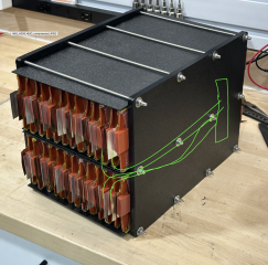
Should come out very neat with a channel of wires routed right up the middle between halves up to the bms no top. (In this pic, the battery is on it's side.)
 

Here I'm removing the taped on blocks that these come with. Propbably relevant to the assembly for the original laser welded plate setup, but when using bolt-through assembly, these make it much harder to fold the tabs onto each other. Removed and you get near complete fold over like this:

IMG_4356.HEIC_compressed.JPEG IMG_4357.HEIC_compressed.JPEG

And one side all done:

IMG_4358.HEIC_compressed.JPEG

I can really see the advantage of making one solid piece (like the PCB variant JG demonstrates in his videos). There's a thread around here where someone takes fiberboard, lasers out the slots and holes, and installed rivnuts for the backer plate. That would also be really nice.

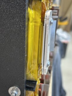
The problem with my approach, is that these plates all move independently of one another, and there's enough give for them to short out. Just wrapping them in fish paper or kapton doesn't seem...sufficient.

I'm going to see if I can print out some spacers to force them to be separated apart, but I'm open to alternative solutions. (Which, honestly, one of them may be to get some fiber board lasered...)
 
The problem with my approach, is that these plates all move independently of one another, and there's enough give for them to short out. Just wrapping them in fish paper or kapton doesn't seem...sufficient.
Damn, that's exactly what I was afraid of.

here's a thread around here where someone takes fiberboard, lasers out the slots and holes, and installed rivnuts for the backer plate. That would also be really nice.
I think that even if you don't mount it rigidly, just using a thin 1.5mm epoxy fiberboard could be enough to space everything evenly. And fiberboard is soft enough that even a hobby cnc should cut it just fine. I personally think that's the best option still.

I'm going to see if I can print out some spacers to force them to be separated apart,

As an alternative, How about making "sleeves" or "covers" for the plates? Right, you just said that. You could cast them in silicone too.

Actually, you could even print a mostly-empty spacing bracket that you'd push from the top as well but over multiple electrodes., wouldn't even need to cover the entire thing, 4 plates at once would be enough. That could have slots for the plates to slide in. Should be easy enough to install but probably a bit more tricky to remove later if it latched mechanically.
 
I just saw it, are you planning to run 26s and vesc labs maxim 120? I think "120" is not the voltage you can run, it's the max voltage on the components. I might be wrong, but something you better check. In that case about 100v battery would be max I think.
 
The problem with my approach, is that these plates all move independently of one another, and there's enough give for them to short out. Just wrapping them in fish paper or kapton doesn't seem...sufficient.
How about 2 blobs of silicone between the plates? After it cures, shorts will be highly unlikely.
 
Back
Top