• Hello ES! We could use some help to get us past the finish line on building the new knowledgebase for the forum.
    Can you donate? Please see our fundraising page. Thank you!

Eahora M1PS Knight Restoration

chuyskywalker

🚴‍♂️ Mega poster
Joined
Sep 8, 2019
Messages
931
Location
USA, CA, Bay Area
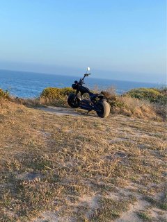
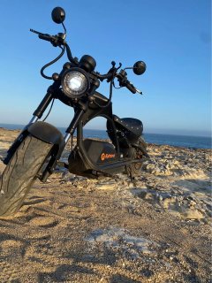
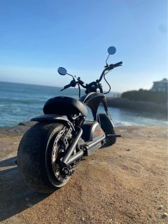
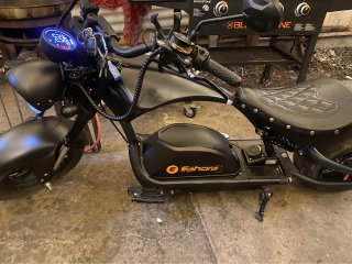
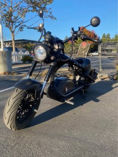
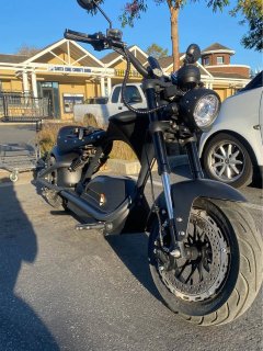
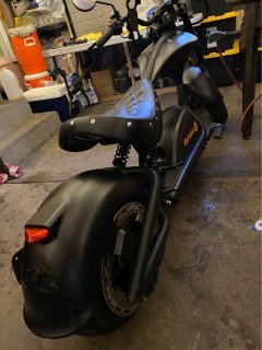
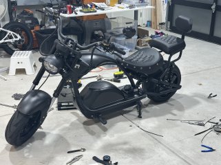
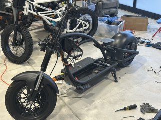
I've been on the lookout for an Eahora** M1PS Knight for a while. Found a guy on marketplace selling it "with a bit of damage", ha!
IMG_3996.HEIC_compressed.JPEG

Pictures from the ad:

1.jpg2.jpg3.jpg4.jpg5.jpg6.jpg8.jpg9.jpg10.jpg13.jpg14.jpg

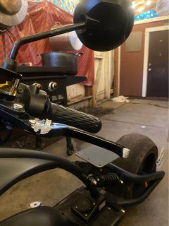
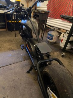
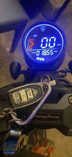
When I went to check it out, blown rear tire and FULLY bald, like 100% had been doing burn outs ;) Odo read about 2500mi, so they definitely got some good use out of it for the last 2 years ownership. Also owned up to laying it down a few time; nothing catastrophic, but clearly had to swap parts out here and there. I suspected that the amount of repair work just exceeded their tolerance.

Regardless, it powered on, motor spun with no issues, and I didn't see any structural issues with the frame. I won't know how the battery is fairing till I get it on a tester, but I'm not super worried about it. This was never tuned to higher amps, and it runs pretty "light" for something this big.

I paid $2400 for it and plan to get it back to fully working condition -- which, to their credit, Eahora does make pretty easy with a large collection of replacement parts available for direct order on their site. It'll set me back another $600 to get a number of things that I've found in need of repair.

Here's the fun fix-it list so far:
  • Rear tire fully wrecked, replacement ordered
  • Rotors are pretty well used, has rust; replacement ordered
  • I don't know the condition of the brake pads, but out of an abundance of caution; replacements ordered
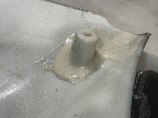
  • The "tank" has one of the bolt bosses of plastic broken off; repaired with ca glue + high strength plastic epoxy to build up some support
  • The keyfob receiver was held on by tape which had dissolved over time; replaced with new doublesided tape
  • Original rear fender wire loom clearly spent some time rubbing elbows with the tire and was worn down to bare wires; ordered replacement
  • The ignition lock lost some retaining screws at some point and the constant motion caused the negative connection to partially separate; depending on which way the steering was turned the bike would turn on/off as the wire made/lost contact; will repair/replace
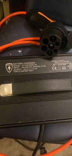
  • The charger had something rattling around inside; cleaned out some broken off plastic retaining rings and vacuumed out about 500 small bugs
  • The headlight is, reportedly, under-powered; will investigate
  • General dust-and-grime cleanup needed; rag and cleaner solution deployed
  • The left brake lever got a good chunk scraped off, but it's not bad enough to warrant replacement, just cosmetic
  • DC breaker was knocked loose from mount and looks to be in rough shape; replacement ordered
So, lots to fix to get it back in condition, but nothing critical and none of it hard to source/fix. I think, even after all the parts and pieces, it'll still have been a good buy, but time will tell.

On a different note: one of the goofiest things I found in this kit is the ABSURD charger plug. It's a full blown "Mennekes (type 2)" plug and socket which only has two of the big pins connected with some 16awg looking wire. That wire then connectorizes into the main harness to get back to the battery with... an XT30 plug! I mean, the charger only puts out 13A, which is technically under "30", but it's pretty silly looking, imo. Plus, it gives off the very wrong impression that you can take this to an EV station -- that would go poorly (not that anything here in my region uses this connector type, but still).

One really nice upside: this is already registered with the local authorities, so I just need to get it transferred and I have something legal to ride, right out the gate. That's a big plus for me, and one of the reasons I was attracted to this particular bike. We'll see if this project derails my fargrin build; there's some very good reasons to scrap that project and move the 96v system onto this one...

Now back to my tinkering as I await parts to arrive.

** Eahora is the US rebranding of Mangosteen in China.
 

Attachments

  • 11.jpg
    11.jpg
    51.5 KB · Views: 8
  • 7.jpg
    7.jpg
    88.8 KB · Views: 11
First little fix, that post which snapped off the tank:

IMG_4019.HEIC_compressed.JPEG
Pretty straight forward -- glad the previous owner left the snapped remains in place, otherwise this would have been an expensive replacement part.

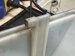
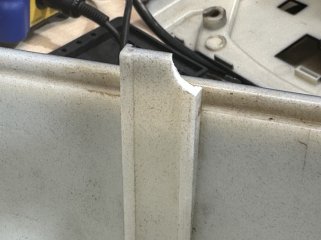
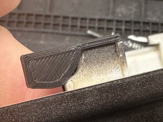
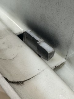
I also found a new broken part: the battery cover has little locking feet and an entire side all had them snapped off.

Here's what they should look like, and a broken one:

IMG_4011.HEIC_compressed.JPEGIMG_4014.HEIC_compressed.JPEG

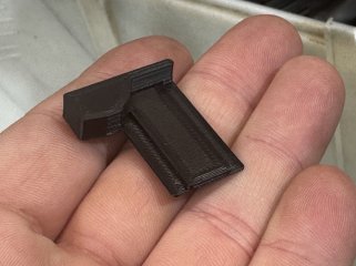
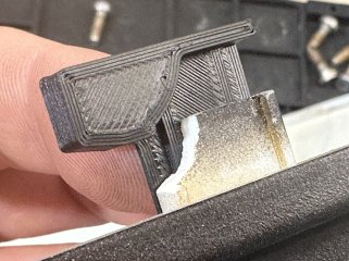
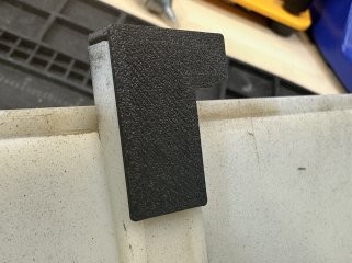
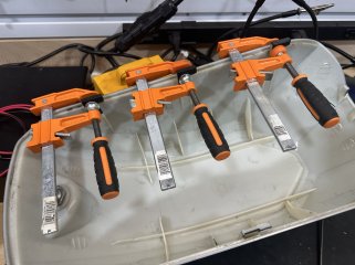
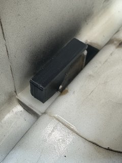
A little bit of measuring, modeling, and printing later and I've got these nice slide-in-place replacements ready to go. Apply a bit of CA glue and clamp them down and these are all sorted out!

IMG_4015.HEIC_compressed.JPEGIMG_4016.HEIC_compressed.JPEGIMG_4017.HEIC_compressed.JPEGIMG_4018.HEIC_compressed.JPEGIMG_4021.HEIC_compressed.JPEGIMG_4022.HEIC_compressed.JPEGIMG_4023.HEIC_compressed.JPEG

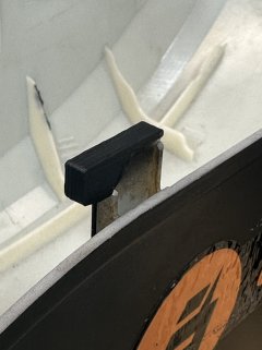
Here's a comparison from under the battery compartment when the lid is on for one of the "stock" feet vs. this 3d printed one on the other side:

IMG_4024.HEIC_compressed.JPEGIMG_4025.HEIC_compressed.JPEG

I don't expect I'll need to replace these pretty much ever -- I'd bet they are as strong as the injection molded ones, if not more so because of their purposeful print orientation.
 
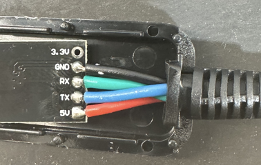
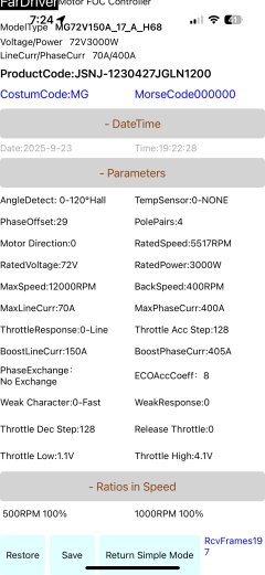
Picked up a fardriver bluetooth interface; did some double checking before I plugged it in, as is wise to do, and found that it was wired for different controller harness. Re-arranged the pins to match positive/negative (5v) and guessed at tx/rx. Of course, got it wrong, but flipped it around and it worked just fine after that.

Screenshot 2025-09-22 at 7.53.12 PM.png
(Doesn't hurt to check inside the bluetooth dongle as well to confirm which wire is which. Never know what crazy color choices might be made.)

The replacement breaker also showed up and I got that put in. It did require some odd work, though. The breaker uses the standard EU DIN rail mount system as the other one, but I'm guessing they violently forced the other one on because the new one did not fit at all. Specifically, there's a piece of bent metal at the bottom of the battery tray that serves as the rail mount. Unfortunately, it's thicker then standard din rail, so it doesn't really "slot in" correctly. A bit of time with a file to add a working bevel fixed that up nicely; fits better than it did before. (Yes, I had to resist the urge to model & 3d print a new mount, lol.)

Finally, I grabbed a set of M6 bolts as this bike uses them all over the place and I feel like I'm missing a few in various places.

Got my shipping notice for the tire and rotors. Checked out a video on how to change the rear tire:


Not, uh, super excited to do this one. (Pretty sure this is the point at which the previous owner threw in the towel.) I think I'll look up some other videos on how to, generally, change tires on really wide wheels -- gotta be workable manual ways to do it.
 
Oh, helpful tip to.

If you are working on the bike and notice the display throwing an E10 error code, do not fret. The display seems to conflict with the bluetooth controller -- nothing explodes, but while the BT is plugged in the display will be in error. Once the the BT is disconnected and the bike is restarted, the display goes back to working as normal.

(Didn't find this advice on google, so I though I'd get it indexed here.)

Is a bit of a bummer since that means I can't just leave the BT plugged in. I may have to adapt the wires to have acome out of the tank if I ever want to debug things. Or maybe make a switch on the 5v line to it so I can toggle it on/off? Not a bad idea that one...

edit: it may be some other reason; apparently it can report E10 when the rear lights are disconnected as well (which mine currently are). Oddly, though, it *did* start working after I restarted the bike with the BT disconnected. So, I'm not 100% sure -- I'll experiment more later -- I definitely want to leave the BT connected.
 
Last edited:
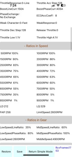
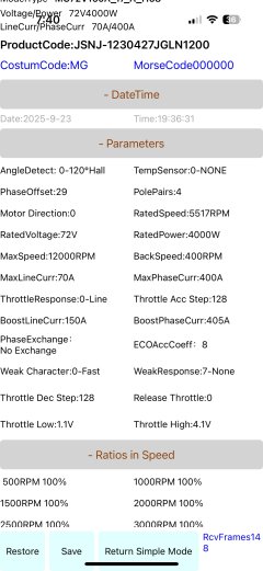
Was playing around with the bike today and wanted to see what the max speed would be without field weakening; which the far driver had turned on already:

IMG_4035.PNG_compressed.JPEGIMG_4037.PNG_compressed.JPEG

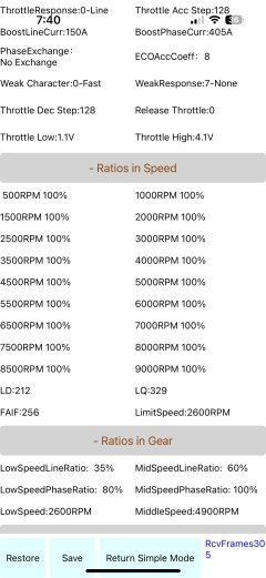
So I turned it "off" like so:

IMG_4045.PNG_compressed.JPEGIMG_4046.PNG_compressed.JPEG
Basically "Weak Response: 7-None" and setting all the "Ratios in speed" to 100%.

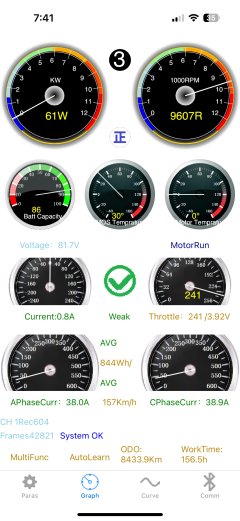
The peak RPM reported on the graph page went from ~7700 to:

IMG_4047.PNG_compressed.JPEG

9600?!?

This is with the motor free spinning in the air. I'm...kinda confused; my understanding would have been that it should be slower with just pure amps and no FW, but it jumped 2000rpm? (Which, if the speedo was correct about the previous top speed being around 60, that means the new top speed would be 75! Now, to be fair, in real world testing, people only hit about 50 on this, but still.)

Anyway, it's a bit baffling.


(Note to self: the display doesn't show a motor temp, but there's a white wire coming off the motor hall bundle. For a hub motor I can't imagine it's anything but a temp sensor. Need to look into that because having a temp sensor and not using is pretty dumb.)
 
Nevermind; these numbers make zero sense. This motor isn't spinning @ 9000rpm, duh. The app has Pole Pairs set to four. This hub motor, without a doubt, does not have 4 pole pairs in it.

I do not understand the logic behind how this was configured at all.
 
(Note to self: the display doesn't show a motor temp, but there's a white wire coming off the motor hall bundle. For a hub motor I can't imagine it's anything but a temp sensor. Need to look into that because having a temp sensor and not using is pretty dumb.)
Multimeter set to ohms will tel lyou if tha'ts a typical ntc sensor. at room tempearature it should be about 10kohms between sensor wire and ground. as temp rises ohms drop, and vice versa.
ptc sensor same but ohms go up with temp, etc.
sometimes the sensors are lm35 which run off the hall power and ground, and output a voltage proportinal to temperature in degrees c,0.01 V/°C, so 10c is 0.1v, 100c is 1v, etc. you can use a voltmeter as a temperature display. ;)
 
There is some sort of explanation of the rpm/pole pairs in the manual. I think you are supposed to have it set to a low number and calculate the real rpm yourself for some reason.
 
There is some sort of explanation of the rpm/pole pairs in the manual. I think you are supposed to have it set to a low number and calculate the real rpm yourself for some reason.
Yeah, I've tried to parse out that section of the manual. Something like "if you don't have X pole pairs, then RPM numbers are scaled by some weird math -- good luck!" Fun. I'm guessing this was done because the controller's internal logic is locked into X/Y/Z buckets of speed ratios and the UI isn't smart enough to make that abstraction for us.

The slightly more readable manual states:
2.6 Current limiting parameter: Adjust the maximum speed by adjusting this parameter.

Let me talk about the conversion of 500RPM, 1000RPM, …8500RPM, 9000RPM in the current limit. These speeds are the speeds of the mid-mounted motor. The corresponding parameter is also the parameter of the central motor. For in-wheel motors, a conversion is required. Usually the number of pole pairs of the in-wheel motor is 16, 20, 24, 28, 30 pairs of poles. Usually the central motor has 4 pairs of poles.

Pole pair ratio of hub motor and mid-mounted motor

Number of pole pairs of hub motor1620242830
And mid-mounted motor pole pair ratio45677.5

After we obtain the pole pair value of a hub motor, we can set the current limiting parameters according to the speed requirements. For example, the pole pair number of the hub motor is 16, divided by 4 to get the pole pair ratio=16/4=4. Then

The actual speed of the 16-pole hub motor corresponding to 500RPM is 125RPM.
The actual speed of the 16-pole hub motor corresponding to 1000RPM is 250RPM.
The actual speed of the 16-pole hub motor corresponding to 4000RPM is 1000RPM.
The actual speed of the 16-pole hub motor corresponding to 5000RPM is 1250RPM.
The actual speed of the 16-pole hub motor corresponding to 5500RPM is 1375RPM.
The actual speed of the 16-pole hub motor corresponding to 6000RPM is 1500RPM.
The actual speed of the 16-pole hub motor corresponding to 6500RPM is 1625RPM

2.7 Magnetic field weakening limit: gradually increase current limit parameters

The current limit value we set should be considered according to actual needs. For a motor with a constant speed of 1000RPM, consider the field weakening depth of 50%. The maximum speed is also considered at 1500RPM, and it is hoped that the motor will not work above 1625RPM. Therefore, the current limit value is set to 30% at 6000RPM, and the speed at 6500RPM and above is set to 5%. This ensures that the motor will weaken the field by 50% when it is idling. It will not cause the motor to shake or even burn control due to excessive field weakening.

For many motors, the field weakening depth can reach 100%, and a 1000RPM motor can work at a high speed of 2000RPM. For this kind of motor, in order to exert higher performance, the current limiting coefficient can be continuously expanded. The current limiting parameter within 8000RPM can be set at the normal value above 70, 8500 is set at 30, and 9000RPM is set at 5.

The setting of the current limit value starts from a safe value and gradually increases the speed. It is necessary to ensure that the field weakening cannot be excessive. Once it is found that the idling speed is unstable or even out of the MOE or OVER protection, it indicates that the speed is too high, the field weakening is excessive, and the parameter needs to be changed back.

The other manual I found is even harder to parse out, tbh.
 
The new tire should be showing up tomorrow; 100% going to be taking it to a shop to have them put it on. I tried getting the old one off and had to resort to a grinder to cut it off. No amount of tricks would force that bad boy off.

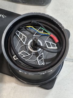
While I had it open, I decided I should take a peak inside the motor. Also I found there was no white wire on the motor side of the hall connector (derp) so there is no temp sensor in here. I plan to remediate that and install one. I might also redo the phases cause I really dislike the stiff core wire used on these, but we'll see.

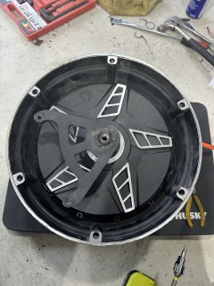
First, remove all the little bolts around the edge on the brake side:
IMG_4049.HEIC_compressed.JPEG

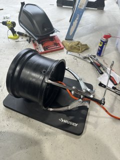
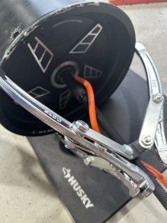
Then, get your big gear puller and lock it in on the other side:

IMG_4050.HEIC_compressed.JPEGIMG_4051.HEIC_compressed.JPEG

Crank away, the brake side will slide out.

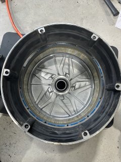
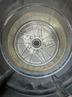
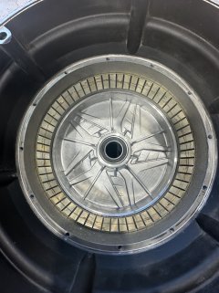
You can now see the inside of the motor:

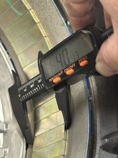
IMG_4052.HEIC_compressed.JPEGIMG_4053.HEIC_compressed.JPEGIMG_4055.HEIC_compressed.JPEG

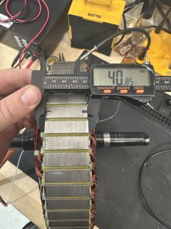
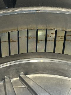
I was a bit surprised to find only 40mm wide magnets. Not...bad, but certainly not nearly as wide as I would have expected to find. I guess it makes sense that this is only rated as a 4000w motor when other motors in this size category are often hitting 15-20kw -- must used the full space to get 60-80mm wide magnets and stator in there.

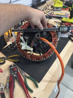
Good to also verify the pole pairs (hence the ultra wide shot) -- counted up 60 magnets, so 30pole pairs.

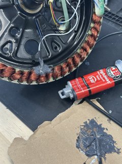
They also certainly didn't skimp on the silicon to plug the wire gap, lol:

IMG_4056.HEIC_compressed.JPEG

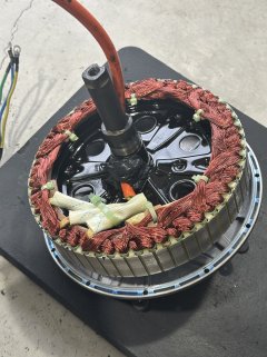
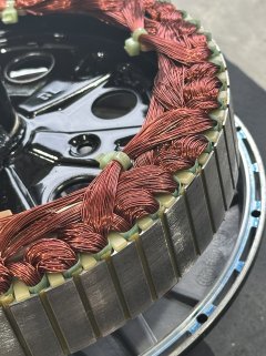
And here's the stator/windings:

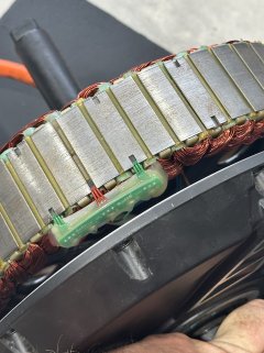
IMG_4058.HEIC_compressed.JPEGIMG_4057.HEIC_compressed.JPEGIMG_4060.HEIC_compressed.JPEG

I think it's kind interesting that the hall sensor board used here...isn't "right". Like, they made it fit, but you can clearly see that the motor has cutouts in the plates for a "wider" hall sensor setup.

---

I'll see if I can snake an extra sensor wire into here to expoxy a temp probe in, then I'll apply some statorade (hey, I've got a spare tube, might as well use it) and close it back up.
 
I was a bit surprised to find only 40mm wide magnets. Not...bad, but certainly not nearly as wide as I would have expected to find. I guess it makes sense that this is only rated as a 4000w motor when other motors in this size category are often hitting 15-20kw -- must used the full space to get 60-80mm wide magnets and stator in there.
Is the stator the same width as the magnets?

I think it's kind interesting that the hall sensor board used here...isn't "right". Like, they made it fit, but you can clearly see that the motor has cutouts in the plates for a "wider" hall sensor setup.
It's possilbe that one or the other setup would be 60 degree hall angle vs 120, and that the controllers they used could'nt deal with whatever the angle would be if they used the actual stator slots.

Or they just didn't want to buy boards long enough for the slot positions (they didn't include the backup set of halls the other side of the motor is slotted for, either, so...), or to pay labor / take time to glue in individual halls and wire them up (vs using a board that makes things more foolproof and less likely to break, etc).
 
Is the stator the same width as the magnets?
It is. I also counted about 30 laminations in 10mm, so an average 0.3mm width, pretty common. Not the best, but not terrible.

The motor is also a little bit larger in diameter, as well, about 255mm compared to the average 203 size, so that helps as well.

IMG_4061.HEIC_compressed.JPEGIMG_4062.HEIC_compressed.JPEGIMG_4063.HEIC_compressed.JPEGIMG_4066.HEIC_compressed.JPEGIMG_4069.HEIC_compressed.JPEGIMG_4071.HEIC_compressed.JPEGIMG_4072.HEIC_compressed.JPEGIMG_4073.HEIC_compressed.JPEGIMG_4074.HEIC_compressed.JPEGIMG_4076.HEIC_compressed.JPEGIMG_4077.HEIC_compressed.JPEG

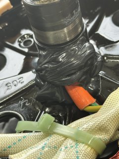
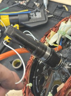
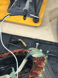
I managed to get enough of the previous silicone out of the way and poke a coat hanger through the bore hole (lots of room!) to feed a temp probe wire inside. Hooked it up to an NTC10k (b3450) and epoxied that under a set of windings. Then taped the wire every 6in or so along the orange wire and wrapped it all in some nylon split loom. Dripped in plenty of statorade as well, snapped the stator back in, and applied a new gasket before the side plate went back on and got bolted up.

I didn't realize until I was totally sealed up that the Fardriver app, as far as I've found so far, doesn't have a way to set the beta value for the temp probe. I also can't find any documentation what-so-ever that specifies what bval it assumes for the NTC probe options. So I have no idea if this will be accurate or if I'll be opening it back up at some point to replace the sensor. Annoying.

I didn't replace the phase wires because they're already pretty big; as thick as the wire in my other 10awg runs, so good enough.

I dropped the motor and tire off at a shop to get it put on; we'll see if they can manage it -- I got a call from them worried it wasn't the right size since they were having trouble getting it on; I clearly made the right choice sending it to somebody with the proper tools.

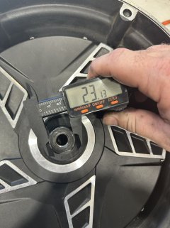
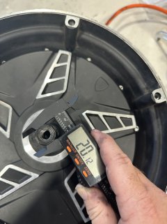
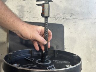
I need to be nice to this motor; it's design quirk with the inset rotor and axle (280mm-ish wide, ~23mm diameter, last 10mm squared at 20mm) seems ultra specific to this bike model. Nothing I've found from QSMotor (who I'm 100% sure make this) matches this style build (there is one that's close, but lacks the rotor setup); and this bike doesn't have dropouts, but bolt-through into sideplates. So, pretty unique, which may become a strong limiting factor in doing any kind of real motor upgrades.
 
Got the wheel&tire back yesterday; took the shop a LOT of work to get it back on, but they did manage it. Gave them a hefty tip so I don't get immediately booted out the door next time I need it done. Really makes some of those 2 part rim + motor setups that QS motors does look appealing! (Regular wheel that uses the bolt lugs to attach to the motor housing.)

Still waiting on some replacement wiring pieces before I can get it all buttoned back up and get started on the fardriver tuning. (Still can't believe it's a 60 magnet motor that they'd setup as a 4 polepair in the app...)
 
It has numerous indisputably prominent Harley-Davidson styling cues. IMHO it just needs some leather handlebar-end tassels to complete the theme.

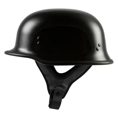
Maybe also a flat black 1/2 helmet?

Highway 21 9mm Helmet
 
If it isn’t, I’ll whip up some plastic export, but CA glue is pretty dang strong.
Different CAs have varying properties, but all of the ones I've used:
--are water soluble
--crystalize and then fracture with temperature cycling

back when I used to build scifi props and models, I'd use CA to glue on the non-plastic bits of junk that couldn't be bolted or screwed on, or melted into the plastic bits. but the ones I didn't have on display in hobby stores / etc that I kept at home with our swamp-cooler "air conditioning" would eventually have those bits start falling off. The ones on display elsewhere stayed intact, with the fairly consistent temperature and low humidity of their normal air conditioning systems.

That was in the 90s, so I'm sure there are differnet formulations of CA nowadays, but the basic idea is still the same, and may still have the same issues.


For any styrene plastics, I've used Plastruct liquid glues to assemble or repair. For other plastics, it depends on the type, for which solvent works better---but solvents that turn them back into a single piece of plastic, rebuilding the long polymer chains, will "always" work better than adhesives that just bond their surfaces to the adhesive itself.

Some plastics don't have a solvent that does this (HDPE, for example), so your'e stuck ;) with glues that will stick to their surfaces, or thermal welding, etc.
 
Screenshot 2025-10-04 at 8.00.04 PM.png

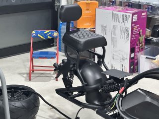
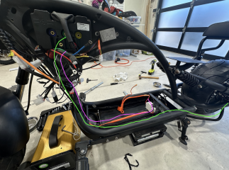
The placement of the controller on this bike is a bit frustrating. The battery starts in the lower section, routes all the way up through a tube to the controller, then the phase wires have to come all the way back down and out to the motor. And the tube you have to shove all of this through is...well, it works, but it's a huge pain in the ass.

The photo is shot pretty wide, so it's a bit deceiving, but you could fit the controller in the deck behind the breaker switch pretty easily. Then it'd just be a small handful for signal wires going through the tube, plus the battery and phase wires would all be a million miles shorter. If I decide to upgrade this bike, that's definitely the plan. With all the space left if the tank, I'll probably drill and install some speakers on top :D

But, after much fishing, shoving, and swearing I got it all through. A bunch of parts came in today as well, so I:
  • Replaced both sets of brake pads; didn't look worn down much at all, but it wasn't a huge cost
  • Replaced the front disc (had already done the rear)
  • Got the motor mounted back up
  • Setup the controller with proper pole pairs and re-did the auto-tune; no issues, proper RPMs now present
  • Replaced the battery connector on the bike (previous one had charring marks)
  • Replaced the ignition key with a new, working one
  • Remove the extended foot pegs (I'm not tall enough for the extension, more comfortable closer for me)
  • Added more preload to the main suspension; had none, added all of it. Could maybe even use stronger springs/shocks, I still squish it down pretty easily.
  • Replaced the old breaker *and* breaker mount (new version is much better; doesn't use an improvised din rail, but just has some thin bolts going through the breaker which hold tight)
I don't have the rear fender (plate, lights, etc) on because I'm missing the "multi wire" that connects all of that to the controller. I contact the company, having ordered it 14 days ago, only to hear back that they are out of stock (despite, annoyingly, being in stock when I ordered...) and won't be here for another 20-30 days. Ugh.

Still, took it for a spin around the block. Mode 1 and 2 are, as one would expect, pretty tame. Mode 3 is definitely how you'd ride around town :)

IMG_4159.HEIC_compressed.JPEG

I have done absolutely zero tuning yet, I have no idea what the top speed is, I don't have any accel/speed benchmarks, etc. Just barely out of the garage at this point, but I'm excited!

I could use some slight more swept back handle bars, for how I sit, I'm kinda stretching to get to the controls; didn't really expect that to be a problem. Will have to investigate options; the lines certainly have some slack to play with, but I've not had to research/order handle bars to these specs before.
 
Too bad that casing between the footpegs isn't the core of a "plasma ball", with the outer edge of the ball being the "toptube", with it's intensity going up and down with torque application. ;)


Then there could be matching subtle lighting strips along the inner circumference of the wheel rims, shining onto the hubs (but the actual lights masked from view with a raised overhanging lip), that also flaried with torque application.
 
Would look cool with this helmet:

5253.jpg
 
IMG_4170.HEIC_compressed.JPEG

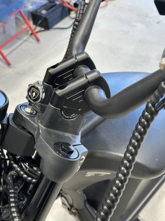
Installed this handle bar extender/riser thing -- shifts the handles towards me enough that it helps with the comfort levels.


Of course, this bike's 1.25 inch mount is slightly off spec such that the mounting holes are maybe 1mm further apart than they should be. A 10mm drill to enlarge the adapter-to-crown holes made it fit with a bit for persuasion.
 
Back
Top