10S custom skate ESC: testers wanted!

furp said:
Hooray it lives! I tested it in my scooter, using the ppm input coming from a modded servo tester, but it seems to work only on duty cycle mode, not on current. Current mode just turns the motor on/off and no speed adjustmend is made. Most of the stuff in the BLDC too I don't understand, but I hope it will just work like this.

One thing I noticed while rewatching vedders video is that even for uploading the firmware per stlink, the VESC is already connected to a battery. When I programmed my first VESC (which tuns out DRV error now), I used only the stlink v2 for flashing it but no external battery power, could that have been the problem?

Lastly, I don't really understand what file to download to get the latest firmware/bldc tool. I can probably just do the download and install commands for bldc tool again and it will get the latest one, right? But I don't know which file to download and chose for updating the firmware via bldc tool.

Furp, if you've purchased a VESC from me, you can use this BLDC tool (for windows): http://ampcite.com/downloads/
and the firmware 1.10 View attachment BLDC_4_ChibiOS.zip that you can flash using ST-Link
You don't need any battery connection if flashing through ST-Link.

Also, Current mode works that way until you put some load on the motor. Try the current mode when standing on the scooter (ready to jump off just in case :D )

Keep in mind that the firmware is meant for the latest VESC (47) hardware which was sold by me, it won't work on older revisions of the VESC

Best wishes, Marcin
 
Marcin said:
Furp, if you've purchased a VESC from me, you can use this BLDC tool (for windows): http://ampcite.com/downloads/
and the firmware 1.10 that you can flash using ST-Link
You don't need any battery connection if flashing through ST-Link.

Also, Current mode works that way until you put some load on the motor. Try the current mode when standing on the scooter (ready to jump off just in case :D )

Keep in mind that the firmware is meant for the latest VESC (47) hardware which was sold by me, it won't work on older revisions of the VESC

Best wishes, Marcin

Is it possible to upload the firmware to a fresh VESC without the bootloader in Windows and not Linux? What I am sensing here by using the STM32 ST-Link program from STMicroelectronics and taking the firmware for the VESC allows the MCU on the VESC to be program through ST-Link, but requires a device with the st-linkV2 for one to proceed?
 
Thanks Marcin, I'll update the tool and firmware later. So I connect the stlink and update firmware to the vesc from bldc tool?

Current control worked really well and with the vesc my small 5065 on 7s is quite powerful on my pneumatic scooter. Got a few more questions tho:
Is there a way to limit the max speed in the software?
Is it possible to have the battery amp limit not be a total power cutoff but just stop acceleration?
Similarly, is there a way to make the lvc cutoff so that when approaching lvc, amps will get limited so the voltage sag wont trigger lvc? I think I hit my lvc at 3.4v per cell under load while the battery is 3.6 per cell without load.

Lastly, is there a way to log the data while riding and readout later at bldc tool?
Thanks!
 
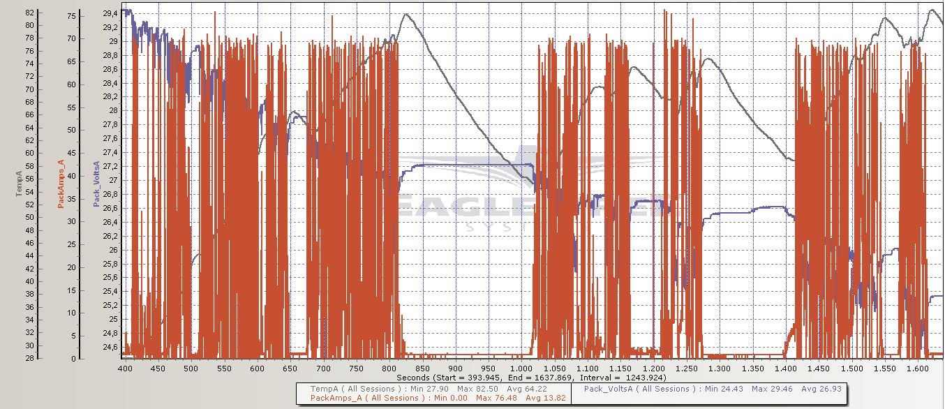
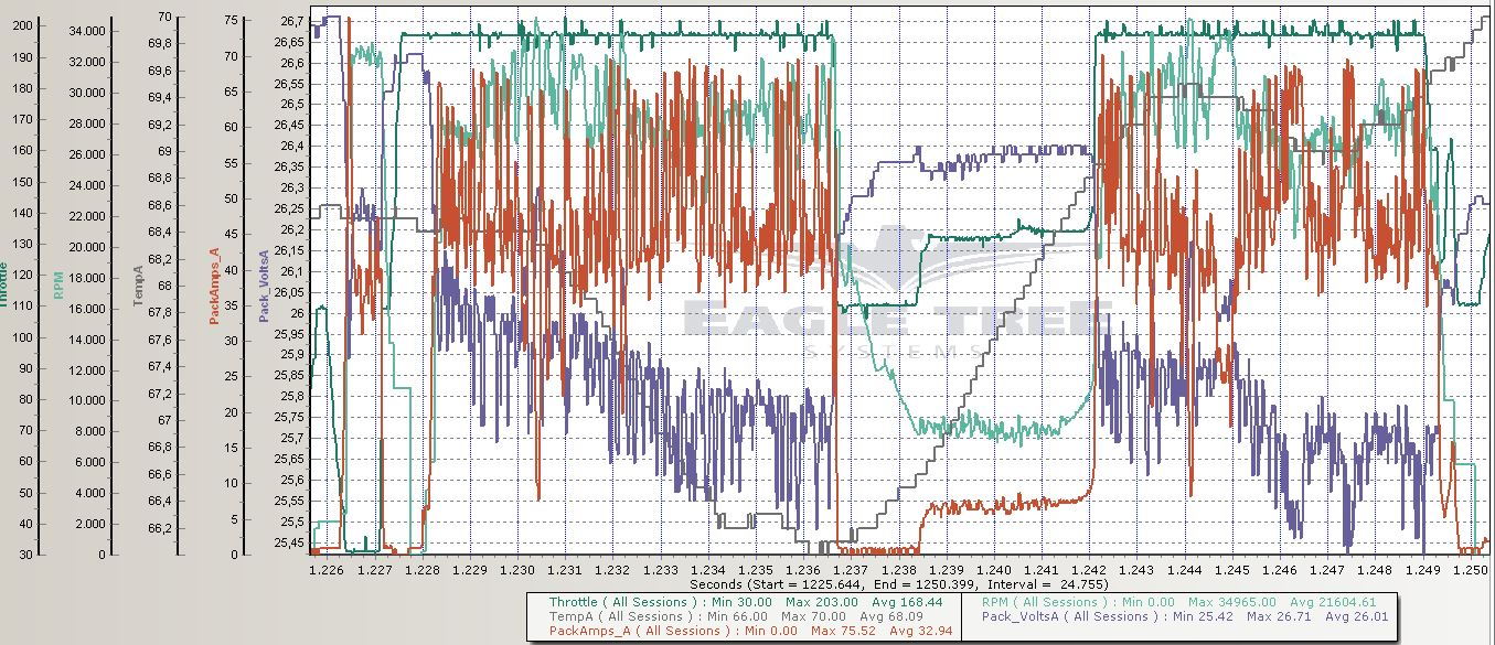
Hi guys, got the diff in my Kyosho fixed and did another test-run (one 7S pack), same gearing as before: 84 km/h no-load @ 3.7 V/Cell (but actual RPM limited to 79 km/h, due to max RPM rating of motor). I increased the Current limits from 80 A to 90 A, which resulted in an average peak Current of around 70 A now: roughly 10 A more than I was seeing with the 80 A limits I ran before. It did increase the number of ABS_OVER_CURRENT faults too, compared to the 80 A limits, but it is still very driveable. Motor is a bit at its limits, hitting 82°C after roughly 7 minutes driving (in ~25°C ambient) and needing cool-downs after that. Highest VESC temp recorded in fault codes was 68°C - being mounted exactly above a 70-80°C motor probably isn't helping much to keep it cool.

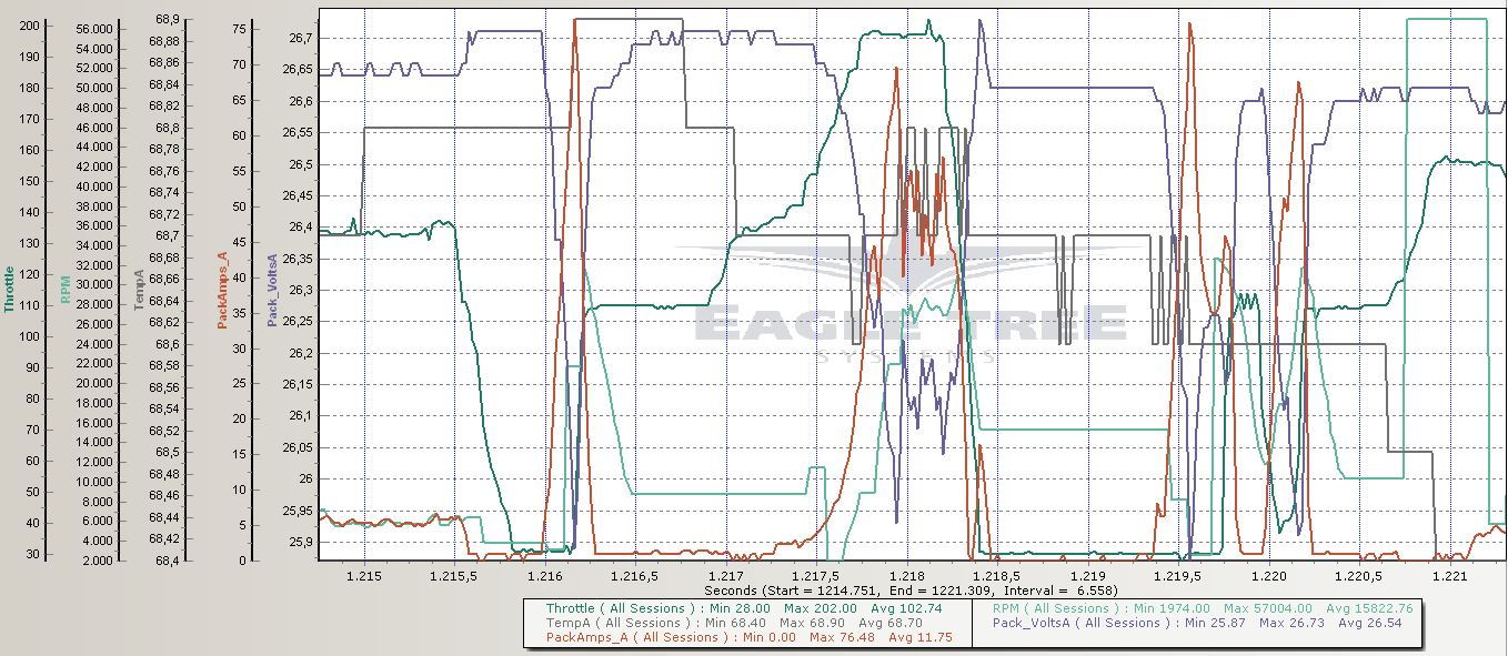
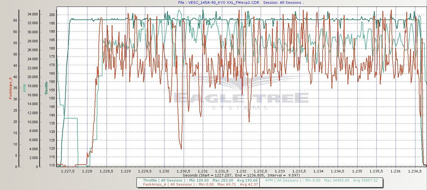
The last log snip shows 2 Current spikes resulting from holding the brake a bit too long, causing the VESC to switch from braking to reverse. These spikes are larger and more abrupt than the Current build-up resulting from how I typically throttle at acceleration myself. While it is quite fun to play around with on sand/gravel, as you can reverse the motor while the car still has forward momentum and throw up a lot of dust, maybe a braking mode like in conventional hobby ESCs, where the ESC only reverses when "double-tapping" the reverse after stand-still, would be nice in order to reduce mechanical/electrical stress a bit more?

Also, if I set soft RPM limits in the App Config/PPM tab, write them to the VESC, then disconnect/reconnect VESC, the numbers are there after read config, but the Soft RPM limit tick-box is not ticked anymore, as if the soft RPM limit is not enabled. Is this a little bug in the tool?

If there's any changes/settings you want me to test, please let me know Benjamin.

Details:
Firmware: VESC_experimental_2.bin

BLDC settings:
Code:
<?xml version="1.0" encoding="UTF-8"?>
<MCConfiguration>
    <pwm_mode>1</pwm_mode>
    <comm_mode>0</comm_mode>
    <motor_type>0</motor_type>
    <sensor_mode>0</sensor_mode>
    <l_current_max>90</l_current_max>
    <l_current_min>-90</l_current_min>
    <l_in_current_max>90</l_in_current_max>
    <l_in_current_min>-20</l_in_current_min>
    <l_abs_current_max>145</l_abs_current_max>
    <l_min_erpm>-100000</l_min_erpm>
    <l_max_erpm>100000</l_max_erpm>
    <l_max_erpm_fbrake>300</l_max_erpm_fbrake>
    <l_max_erpm_fbrake_cc>1500</l_max_erpm_fbrake_cc>
    <l_min_vin>8</l_min_vin>
    <l_max_vin>50</l_max_vin>
    <l_slow_abs_current>1</l_slow_abs_current>
    <l_rpm_lim_neg_torque>1</l_rpm_lim_neg_torque>
    <l_temp_fet_start>80</l_temp_fet_start>
    <l_temp_fet_end>100</l_temp_fet_end>
    <l_temp_motor_start>80</l_temp_motor_start>
    <l_temp_motor_end>100</l_temp_motor_end>
    <l_min_duty>0.005</l_min_duty>
    <l_max_duty>0.95</l_max_duty>
    <sl_min_erpm>150</sl_min_erpm>
    <sl_min_erpm_cycle_int_limit>1100</sl_min_erpm_cycle_int_limit>
    <sl_max_fullbreak_current_dir_change>10</sl_max_fullbreak_current_dir_change>
    <sl_cycle_int_limit>65</sl_cycle_int_limit>
    <sl_cycle_int_limit_high_fac>0.6</sl_cycle_int_limit_high_fac>
    <sl_cycle_int_rpm_br>60000</sl_cycle_int_rpm_br>
    <sl_bemf_coupling_k>800</sl_bemf_coupling_k>
    <hall_table_0>-1</hall_table_0>
    <hall_table_1>1</hall_table_1>
    <hall_table_2>3</hall_table_2>
    <hall_table_3>2</hall_table_3>
    <hall_table_4>5</hall_table_4>
    <hall_table_5>6</hall_table_5>
    <hall_table_6>4</hall_table_6>
    <hall_table_7>-1</hall_table_7>
    <hall_sl_erpm>2000</hall_sl_erpm>
    <s_pid_kp>0.0001</s_pid_kp>
    <s_pid_ki>0.002</s_pid_ki>
    <s_pid_kd>0</s_pid_kd>
    <s_pid_min_rpm>900</s_pid_min_rpm>
    <p_pid_kp>0.0001</p_pid_kp>
    <p_pid_ki>0.002</p_pid_ki>
    <p_pid_kd>0</p_pid_kd>
    <cc_startup_boost_duty>0.05</cc_startup_boost_duty>
    <cc_min_current>1</cc_min_current>
    <cc_gain>0.0046</cc_gain>
    <cc_ramp_step_max>0.04</cc_ramp_step_max>
    <m_fault_stop_time_ms>2000</m_fault_stop_time_ms>
    <meta_description><!DOCTYPE HTML PUBLIC "-//W3C//DTD HTML 4.0//EN" "http://www.w3.org/TR/REC-html40/strict.dtd">
<html><head><meta name="qrichtext" content="1" /><style type="text/css">
p, li { white-space: pre-wrap; }
</style></head><body style=" font-family:'MS Shell Dlg 2'; font-size:8.25pt; font-weight:400; font-style:normal;">
<p style=" margin-top:0px; margin-bottom:0px; margin-left:0px; margin-right:0px; -qt-block-indent:0; text-indent:0px;">Configuration loaded from the motor controller.</p></body></html></meta_description>
</MCConfiguration>


Fault codes:
Code:
The following faults were registered since start:

Fault            : FAULT_CODE_ABS_OVER_CURRENT
Current          : -119.0
Current filtered : 146.7
Voltage          : 29.61
Duty             : 0.43
RPM              : 26162.4
Tacho            : 90878
Cycles running   : 3116
TIM duty         : 3816
TIM val samp     : 2299
TIM current samp : 6762
TIM top          : 8926
Comm step        : 3
Temperature      : 31.05

Fault            : FAULT_CODE_ABS_OVER_CURRENT
Current          : -19.7
Current filtered : 145.1
Voltage          : 29.16
Duty             : 0.07
RPM              : 23469.9
Tacho            : 98380
Cycles running   : 4713
TIM duty         : 2141
TIM val samp     : 1125
TIM current samp : 15921
TIM top          : 29593
Comm step        : 5
Temperature      : 32.88

Fault            : FAULT_CODE_ABS_OVER_CURRENT
Current          : -18.5
Current filtered : -150.8
Voltage          : 29.13
Duty             : 0.71
RPM              : 21749.2
Tacho            : 118731
Cycles running   : 21936
TIM duty         : 4077
TIM val samp     : 2060
TIM current samp : 4917
TIM top          : 5714
Comm step        : 4
Temperature      : 33.68

Fault            : FAULT_CODE_ABS_OVER_CURRENT
Current          : -153.2
Current filtered : 145.9
Voltage          : 29.64
Duty             : 0.42
RPM              : 27695.6
Tacho            : 134954
Cycles running   : 9744
TIM duty         : 3812
TIM val samp     : 2372
TIM current samp : 6859
TIM top          : 8974
Comm step        : 3
Temperature      : 35.48

Fault            : FAULT_CODE_ABS_OVER_CURRENT
Current          : -15.3
Current filtered : -152.8
Voltage          : 29.10
Duty             : 0.72
RPM              : 22580.9
Tacho            : 156825
Cycles running   : 29314
TIM duty         : 4080
TIM val samp     : 2056
TIM current samp : 4891
TIM top          : 5670
Comm step        : 4
Temperature      : 37.66

Fault            : FAULT_CODE_ABS_OVER_CURRENT
Current          : -80.0
Current filtered : 145.3
Voltage          : 27.38
Duty             : 0.02
RPM              : 22189.0
Tacho            : 1240588
Cycles running   : 1176
TIM duty         : 991
TIM val samp     : 523
TIM current samp : 22415
TIM top          : 43784
Comm step        : 5
Temperature      : 31.18

Fault            : FAULT_CODE_ABS_OVER_CURRENT
Current          : 30.0
Current filtered : 146.8
Voltage          : 25.81
Duty             : 0.70
RPM              : 55465.8
Tacho            : 1578151
Cycles running   : 36596
TIM duty         : 4069
TIM val samp     : 2038
TIM current samp : 4940
TIM top          : 5804
Comm step        : 4
Temperature      : 62.13

Fault            : FAULT_CODE_ABS_OVER_CURRENT
Current          : 33.3
Current filtered : 148.7
Voltage          : 25.67
Duty             : 0.70
RPM              : 55479.4
Tacho            : 1775224
Cycles running   : 248169
TIM duty         : 4066
TIM val samp     : 2037
TIM current samp : 4955
TIM top          : 5837
Comm step        : 5
Temperature      : 31.24

Fault            : FAULT_CODE_ABS_OVER_CURRENT
Current          : 31.0
Current filtered : 147.2
Voltage          : 25.25
Duty             : 0.70
RPM              : 54756.6
Tacho            : 2231035
Cycles running   : 142816
TIM duty         : 4067
TIM val samp     : 2037
TIM current samp : 4954
TIM top          : 5834
Comm step        : 4
Temperature      : 66.52

Fault            : FAULT_CODE_ABS_OVER_CURRENT
Current          : 29.8
Current filtered : 145.2
Voltage          : 25.11
Duty             : 0.70
RPM              : 53739.8
Tacho            : 2277217
Cycles running   : 272095
TIM duty         : 4068
TIM val samp     : 2038
TIM current samp : 4945
TIM top          : 5815
Comm step        : 4
Temperature      : 67.04

Fault            : FAULT_CODE_ABS_OVER_CURRENT
Current          : 47.5
Current filtered : 145.7
Voltage          : 24.93
Duty             : 0.00
RPM              : 2332.2
Tacho            : 2447109
Cycles running   : 1941
TIM duty         : 263
TIM val samp     : 131
TIM current samp : 26505
TIM top          : 52747
Comm step        : 6
Temperature      : 68.27

Log:
dr_t-albums-kyosho-scorpion-xxl-picture32714-vesc-145a-90a-kyo-xxl-230813-all.jpg


dr_t-albums-kyosho-scorpion-xxl-picture32715-vesc-145a-90a-kyo-xxl-230813-snip1.jpg


dr_t-albums-kyosho-scorpion-xxl-picture32716-vesc-145a-90a-kyo-xxl-230813-snip2.jpg
 
furp said:
Is there a way to limit the max speed in the software?

What input device are you using? The App Config/PPM and ADC tabs have Soft RPM limit settings. I use an RC radio (PPM) and am using the soft RPM limits in that tab to keep the motor from revving up beyond the manufacturer's recommended max RPM.

furp said:
Similarly, is there a way to make the lvc cutoff so that when approaching lvc, amps will get limited so the voltage sag wont trigger lvc? I think I hit my lvc at 3.4v per cell under load while the battery is 3.6 per cell without load.

You sure you want to drain your batteries beyond 3.6V/Cell? I accidentally happened to do that too tonight, and had to charge it back to >3.6V/Cell in NiMH mode, because in LiPo mode the charger did not recognize it anymore... Below 3.6V/Cell most juice is out of the battery anyway and Voltage will start to drop rapidly under load.

I just use a simple low-Voltage alarm like this, which has user set Voltage alarm levels: http://www.hobbyking.com/hobbyking/store/__42757__HobbyKing_8482_Cell_Checker_with_Low_Voltage_Alarm_2S_8S_EU_Warehouse_.html

18588(1).jpg


furp said:
Lastly, is there a way to log the data while riding and readout later at bldc tool?

Very interested in this too. You can use the videologger tool, but you have to connect a computer with a camera for that. Benjamin mentioned he was working on a solution to capture the videologger data through Bluetooth somehow, but I don't know the details of that.
 
I am using a PPm input from a modded servo tester. Just found the soft rpm limit, missed it before :) Gonna limit the rpm a bit, 35kmh on a wobbly scooter feels less safe than on an eboard.

You are probably right about draining the batteries, I was just a little frustrated about the sudden cutoff of power. My cells (recycled from makita konion packs) should have 3-4.2v voltage range, but I am not sure about the range of my liion ebike charger. On my testrun today it turned out to be about 9km range on a 4.5Ah (probably a little less) 7s pack which seems quite good to me. It would be sweet to have a tiny led bar and code add on to the vesc for a battery gauge tho.

Would be sweet to have the realtime data logged on a smartphone!
 
I have two vesc tested and ready to ship if anyone is looking for one. I lowered my price for a limited time. These are updated to handle 200kv+ motors and 12s battery. I have no issue's with my 270kv motor and 12s. Check it out.

https://endless-sphere.com/forums/viewtopic.php?f=31&t=68421&p=1031508#p1031508
 
Dr_T said:
Hi guys, got the diff in my Kyosho fixed and did another test-run (one 7S pack), same gearing as before: 84 km/h no-load @ 3.7 V/Cell (but actual RPM limited to 79 km/h, due to max RPM rating of motor). I increased the Current limits from 80 A to 90 A, which resulted in an average peak Current of around 70 A now: roughly 10 A more than I was seeing with the 80 A limits I ran before. It did increase the number of ABS_OVER_CURRENT faults too, compared to the 80 A limits, but it is still very driveable. Motor is a bit at its limits, hitting 82°C after roughly 7 minutes driving (in ~25°C ambient) and needing cool-downs after that. Highest VESC temp recorded in fault codes was 68°C - being mounted exactly above a 70-80°C motor probably isn't helping much to keep it cool.

The last log snip shows 2 Current spikes resulting from holding the brake a bit too long, causing the VESC to switch from braking to reverse. These spikes are larger and more abrupt than the Current build-up resulting from how I typically throttle at acceleration myself. While it is quite fun to play around with on sand/gravel, as you can reverse the motor while the car still has forward momentum and throw up a lot of dust, maybe a braking mode like in conventional hobby ESCs, where the ESC only reverses when "double-tapping" the reverse after stand-still, would be nice in order to reduce mechanical/electrical stress a bit more?

Also, if I set soft RPM limits in the App Config/PPM tab, write them to the VESC, then disconnect/reconnect VESC, the numbers are there after read config, but the Soft RPM limit tick-box is not ticked anymore, as if the soft RPM limit is not enabled. Is this a little bug in the tool?

If there's any changes/settings you want me to test, please let me know Benjamin.

Thanks for the update! I noticed the checkbox bug and fixed it, I will push it to github later.

Yesterday I was testing the RC car again and found a problem that would decrease the average output power significantly. It was the current backoff that had way too much gain for a motor with this inductance and resistance, so every time it activated it would reduce the duty cycle so much that the current would even go past zero to braking for an instant. After decreasing it, the power with 110A current limit was much higher. Even when geared for 150km/h on my 3.9kg 4wd buggy, full throttle makes all wheels spin on asphalt. Before that I could give full throttle without loosing traction on asphalt, so the difference is big. I have updated BLDC Tool and the code so that the backoff gain and some other things can be changed from BLDC Tool, so it can be tuned for these motors. Is it possible for you to build and install the linux version of bldc tool so that you can pull the latest version?

hi Marcin, is it possible to upload/flash the 1.10 firmware on the VESC (1.8 installed) using the BLDC tool or do I need a STLinkv2 ?
Marcin, you should really upload the bootloader to the VESCs as well since updating the firmware from BLDC Tool is so convenient. When pulling the latest version of BLDC Tool for linux from my github, the latest compiled firmware is included in the firmwares directory.

I could make a button in BLDC Tool that attempts to write the bootloader to the VESC with the firmware it has now, but I don't know if it will work since the flash memory has to be erased before it can be written and I haven't implemented support for erasing the bootloader sector in the current firmware. In a future firmware I can implement support to update the bootloader from BLDC Tool as well so that only the firmware has to be installed from the beginning.

You are probably right about draining the batteries, I was just a little frustrated about the sudden cutoff of power. My cells (recycled from makita konion packs) should have 3-4.2v voltage range, but I am not sure about the range of my liion ebike charger. On my testrun today it turned out to be about 9km range on a 4.5Ah (probably a little less) 7s pack which seems quite good to me. It would be sweet to have a tiny led bar and code add on to the vesc for a battery gauge tho.

Would be sweet to have the realtime data logged on a smartphone!

A soft battery cutoff is a feature that I also would like to have. Braking should always work since it does not drain the battery, but acceleration can be decreased based on the battery voltage. I will have a look at this for the next firmware.

Logging data on the VESC during a ride is possible to some extent, but there is not enough space available in RAM for doing that at a high rate. Logging over bluetooth works and the video logger cal also just write data to text files. You could, for example, connect a raspberry pi to the USB port and just log everything in text files. Video logging has been very useful for me since I can see what is going on when and where. I need to write some tutorials for logging in general.
 
I have implemented soft battery cutoff and pushed the latest BLDC Tool and firmware to github. It works by setting two voltage levels: one where the battery current is starting to get limited and one where it is completely off. Between these voltages, the allowed battery current will be proportional to where the voltage is. For example, the beginning limit can be 3.4V per cell and the ending limit can be 2.9V per cell. Negative (regenerative braking) current will not be affected, so when the battery runs out you will still have brakes.

The parameters that can be changed for the RC motors are also in this version of BLDC Tool. Dr_T: if you can make the latest BLDC Tool run, I can help you with which settings to change.

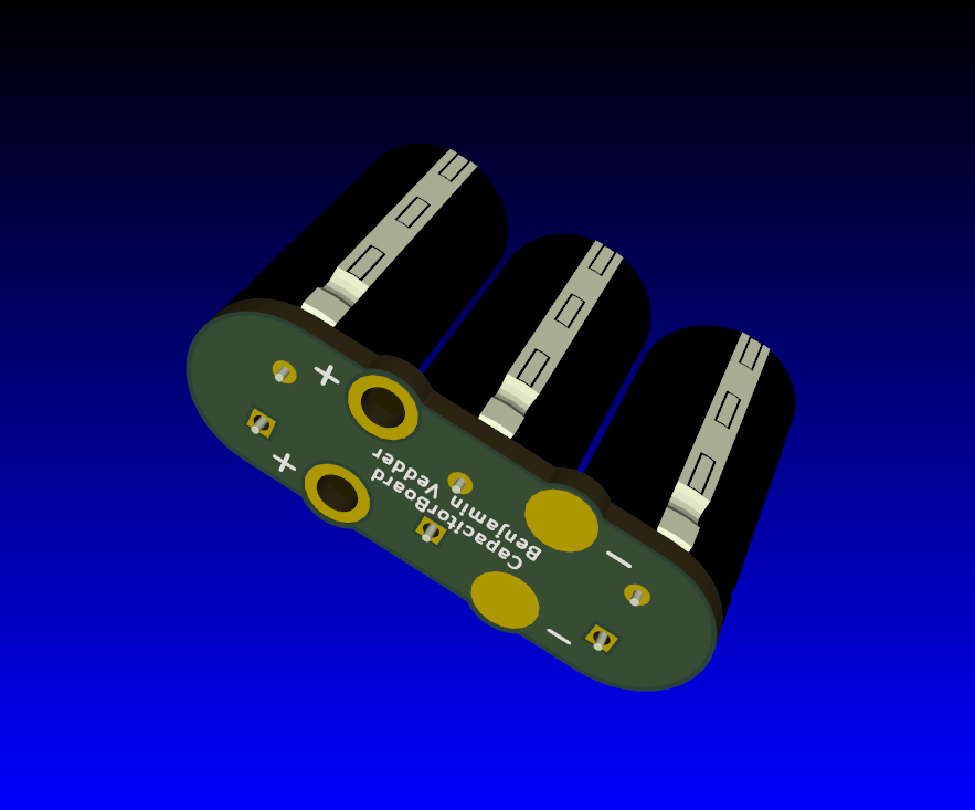
Another thing: I got the capacitor PCBs:
IMG_4853.JPG

IMG_4854.JPG

CapPcb_3d_caps.png


The capacitor PCB can also be placed under the VESC it it fits better that way (this will also put the caps closer, which is good)
 
SWEET VEDDER.... three caps in parallel is much better. but now only 1680 total. I suppose this is the biggest three caps that can fit side-by-side whilst not increasing the total width of the assembly.
 
furp said:
Thanks Marcin, I'll update the tool and firmware later. So I connect the stlink and update firmware to the vesc from bldc tool?

Current control worked really well and with the vesc my small 5065 on 7s is quite powerful on my pneumatic scooter. Got a few more questions tho:
Is there a way to limit the max speed in the software?
Is it possible to have the battery amp limit not be a total power cutoff but just stop acceleration?
Similarly, is there a way to make the lvc cutoff so that when approaching lvc, amps will get limited so the voltage sag wont trigger lvc? I think I hit my lvc at 3.4v per cell under load while the battery is 3.6 per cell without load.

Lastly, is there a way to log the data while riding and readout later at bldc tool?
Thanks!

Oops, forgot to subscribe to this thread. You can indeed flash the new firmware through USB using the BLDC tool with-out ST-link
If however you are unable to flash it using USB, I can provide you a in depth tutorial on how to flash it from a Windows machine (Just PM me for info) using ST-Link

Best wishes, Marcin
 
sl33py said:
What is the advantage of 3 smaller caps vs one larger cap? Total capacity is less as onloop noted, is that a concern?

I believe This is done purely as a method to make the vesc more compact.. the 2200uf cap was ridiculous.

With the three caps grouped together it shortens the total length required to house the vesc. It's also thinner.
 
onloop said:
sl33py said:
What is the advantage of 3 smaller caps vs one larger cap? Total capacity is less as onloop noted, is that a concern?

I believe This is done purely as a method to make the vesc more compact.. the 2200uf cap was ridiculous.

With the three caps grouped together it shortens the total length required to house the vesc. It's also thinner.

While total microfarad is much less than a single 2000uf cap being used. One benefit for Vedder to do this is probably the amount of ripple current three caps in parallel can handle versus a single capacitor. There's information about this already.

I just checked the specs of the capacitor Vedder has on pic from Nichicon, the HE(M) series are low impedance rated between 4000 hours and 10000.
http://www.nichicon.co.jp/english/products/pdfs/e-he.pdf
 
chuttney1 said:
onloop said:
sl33py said:
What is the advantage of 3 smaller caps vs one larger cap? Total capacity is less as onloop noted, is that a concern?

I believe This is done purely as a method to make the vesc more compact.. the 2200uf cap was ridiculous.

With the three caps grouped together it shortens the total length required to house the vesc. It's also thinner.

While total microfarad is much less than a single 2000uf cap being used. One benefit for Vedder to do this is probably the amount of ripple current three caps in parallel can handle versus a single capacitor. There's information about this already.

I just checked the specs of the capacitor Vedder has on pic from Nichicon, the HE(M) series are low impedance rated between 4000 hours and 10000.
http://www.nichicon.co.jp/english/products/pdfs/e-he.pdf

This was mostly to make it more compact, but as you correctly point out these caps will have lower total ESR and can handle more ripple current. Here is the PCB on github:
https://github.com/vedderb/CapPCB
Soldering it is easy and there are some capacitor mouser numbers that should work in the README.md.
 
Cool Benjamin! So seems like that could be the explanation for the power throughput being slightly lower than what should have been expected based on the Current limits alone. Looking forward to testing the new Current back-off settings. I'll see what I can do, I did make a bootable thumbdrive with Linux once but was struggling a bit to get the BLDC installed, and then got saved by Jacob's Win version (hint, hint, :D) so didn't put more effort in getting the linux working. I am going on vacation tomorrow, but with a bit of luck there will be enough space left to take the Kyosho. Got some cool new sandpaddle tires for use on beach, that should be able to generate some nice big loads :).

Regarding the aggressive Current back-off: is the RPM limit using the same back-off gains? I was wondering if the heavy Current fluctuations I see, for instance in plot below (90A limit, Soft RPM limits 30-35k), are mainly the result of the fluctuating off-road load alone, or more a combination of the back-off strategies dynamics (resulting from both Current and RPM limits) and the fluctuating loads that come with the inconsistent off-road traction?

Logging tutorial is a great idea too! We need more datas!!! :D

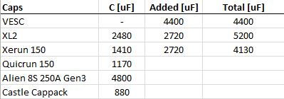
Regarding the caps discussion, below's a quick little overview of the total Capacitance of the stock anti-ripple caps of some hobby ESCs I know of, as reference, and the amount I have added to the ones I own. Here's Castle Creations' boss talking about ripple Voltage and adding Capacitance to hobby ESCs: https://www.rc-monster.com/forum/showpost.php?p=429895&postcount=4, he basically says you can't add to much Capacitance, but there's diminishing returns above about 1.2mf, which correlates with what is found in the typical 1/8 ESCs. In the end it seems the power demands of the motor/load and the ability of the battery to fulfill that, is what determines the ripple Voltage and as a result, how much (extra) Capacitance is needed to increase ESC robustness/survivability.

dr_t-albums-kyosho-scorpion-xxl-picture32738-current-load-fluctuation.jpg


dr_t-albums-various-picture32856-esc-caps.jpg
 
Bad news about 12s and 200+kv motors. It worked fine for me on my first test run but today I took a distance run and it works fine until the cells hit about 3.8v, then it cuts off with the drv8302 error. I would assume this is the electrical rpm that vedder talked about. Running 6s I notice that in 3.9v-4.2v range there is no bursts of power at certain point in the motor's rpm. When it is under 3.9v after I hit around 15mph I feel the motor kick like I put extra throttle, 15mph is also about the point where I would get the drv8302 error with 12s. So I assume if I can somehow get rid of that burst of power (electrical rpm?) then it will work. I notice now that I have a much higher integrator limit with 12s vs the 6s settings I had it on, going to try changing that next time.
 
silviasol said:
Bad news about 12s and 200+kv motors. It worked fine for me on my first test run but today I took a distance run and it works fine until the cells hit about 3.8v, then it cuts off with the drv8302 error. I would assume this is the electrical rpm that vedder talked about. Running 6s I notice that in 3.9v-4.2v range there is no bursts of power at certain point in the motor's rpm. When it is under 3.9v after I hit around 15mph I feel the motor kick like I put extra throttle, 15mph is also about the point where I would get the drv8302 error with 12s. So I assume if I can somehow get rid of that burst of power (electrical rpm?) then it will work. I notice now that I have a much higher integrator limit with 12s vs the 6s settings I had it on, going to try changing that next time.

The power burst that you are feeling is caused by the current measurement problem that I have tried to solve recently. What happens is that at a certain duty cycle (around 80%) one of the shunts will get noise coupled which causes an offset so that too hich current is measured for one commutation cycle and the current backoff kicks in. After this noise disappears the backoff will go back and you feel the kick that you described. With the recent firmwares I have been working on the sample synchronization and some other things to make it better in software, but a hardware solution would be better (by the way, this would not be a problem using three shunts, but using two is more tricky). I did manage to get rid of much of the hardware problem with a patch:
http://home.vedder.se/public/pictures/VESC_Shunts/mod_fix_1.jpg
http://home.vedder.se/public/pictures/VESC_Shunts/mod_fix_2.jpg
New PCBs with VESC version 4.8 are on their way and I will probably receive them next week. I have routed the shunt sense traces differently and made several other changes and cleanups (e.g. replaced the pwr_comm connector with a 7 pin connector so that the NRF can be connected only using that one). If the new hardware works I will push the changes to github. Even with the old hardware, the latest firmware will decrease the power burst and I can probably make it even a bit better.

Now, the DRV fault is probably not caused by the power burst. On the VESC that I worked on I did not double all capacitors, just the ones before the logic ground (there are two, one 15uF 100V and one 10uF 50V). I don't know what the optimal patch is, which is why I haven't uploaded pictures yet, but if just the logic caps are doubled it can even become worse. Putting the electrolytic capacitors closer also helps, which is easy to do with the new cap PCB. The version 4.8 hardware also has some plane and routing improvements that should help against the drv faults, but I'll see about that next week.
 
Thanks vedder and Marcin, you provide great support for my dumb questions! So I understand that ChibiOS is the file to chose for the new firmware, can I just download that from github manually and chose it in the bldc tool? I am using Ubuntu but am not really familiar with it and dont really know how the whole github thing works.
 
Hey guys, I'm following this keenly as my FVT esc's are having issues of tripping on the low voltage cutoff when I floor it (running dual 63mm hub motors on 5s). I'm looking at boosting the whole system to 12s in the future, as well as getting new batts etc to fit my latest deck.

My question is I'm keen to get 2 vesc's shipped to Australia or built here (I know a few guys locally), and I've seen reference to a BOM later than the 4.5, but can't seem to find it in vedders blog? Could someone please link me directly/post them in the OP to the latest version of the BOM, schematics, boards design so I can send it to my manufacturer? Also, if you soon will/have vesc stock and can hook me up, please pm me!

Thanks a heap guys! keen to try the vesc in hubs as soon as funds allow!
 
bandaro said:
Hey guys, I'm following this keenly as my FVT esc's are having issues of tripping on the low voltage cutoff when I floor it (running dual 63mm hub motors on 5s). I'm looking at boosting the whole system to 12s in the future, as well as getting new batts etc to fit my latest deck.

My question is I'm keen to get 2 vesc's shipped to Australia or built here (I know a few guys locally), and I've seen reference to a BOM later than the 4.5, but can't seem to find it in vedders blog? Could someone please link me directly/post them in the OP to the latest version of the BOM, schematics, boards design so I can send it to my manufacturer? Also, if you soon will/have vesc stock and can hook me up, please pm me!

Thanks a heap guys! keen to try the vesc in hubs as soon as funds allow!

Most updated BOM is found under "design" as an BLDC4.7_BOM.ods https://github.com/vedderb/bldc-hardware/blob/master/design/BLDC4.7_BOM.ods
in the Hardware of Vedder's github.
 
bandaro said:
Hey guys, I'm following this keenly as my FVT esc's are having issues of tripping on the low voltage cutoff when I floor it (running dual 63mm hub motors on 5s). I'm looking at boosting the whole system to 12s in the future, as well as getting new batts etc to fit my latest deck.

My question is I'm keen to get 2 vesc's shipped to Australia or built here (I know a few guys locally), and I've seen reference to a BOM later than the 4.5, but can't seem to find it in vedders blog? Could someone please link me directly/post them in the OP to the latest version of the BOM, schematics, boards design so I can send it to my manufacturer? Also, if you soon will/have vesc stock and can hook me up, please pm me!

Thanks a heap guys! keen to try the vesc in hubs as soon as funds allow!


in 7 days ill finally get my next batch of 110, but only 15 left of that. http://www.enertionboards.com/electric-skateboard-parts/vesc-motor-controller/
 
vedder said:
I did manage to get rid of much of the hardware problem with a patch:
http://home.vedder.se/public/pictures/VESC_Shunts/mod_fix_1.jpg
http://home.vedder.se/public/pictures/VESC_Shunts/mod_fix_2.jpg
I would like to reproduce this, because I already have 10 VESCs waiting to be patched. Can you please share another picture of the patch with the full PCB? Did you patch both shunts?
replaced the pwr_comm connector with a 7 pin connector so that the NRF can be connected only using that one
How can the nRF24L01+ be connected to the current VESC 4.7, I didn't find any pinout.

Finally, the latest BLDC_Tool has a UDP connection option. How does that exactly work? Should we have a UDP server that routs the packages from VESC to BLDC_Tool? It would be great to have some example UDP server or description of the connection protocol.


Thanks for keeping up the updates Benjamin, looking forward to VESC 4.8 with FOC and possibly position controlled BLDC motors.
Erwin
 
Back
Top