10S custom skate ESC: testers wanted!

erwincoumans said:
vedder said:
I did manage to get rid of much of the hardware problem with a patch:
http://home.vedder.se/public/pictures/VESC_Shunts/mod_fix_1.jpg
http://home.vedder.se/public/pictures/VESC_Shunts/mod_fix_2.jpg
I would like to reproduce this, because I already have 10 VESCs waiting to be patched. Can you please share another picture of the patch with the full PCB? Did you patch both shunts?
replaced the pwr_comm connector with a 7 pin connector so that the NRF can be connected only using that one
How can the nRF24L01+ be connected to the current VESC 4.7, I didn't find any pinout.

Finally, the latest BLDC_Tool has a UDP connection option. How does that exactly work? Should we have a UDP server that routs the packages from VESC to BLDC_Tool? It would be great to have some example UDP server or description of the connection protocol.


Thanks for keeping up the updates Benjamin, looking forward to VESC 4.8 with FOC and possibly position controlled BLDC motors.
Erwin

I would like to reproduce this, because I already have 10 VESCs waiting to be patched. Can you please share another picture of the patch with the full PCB? Did you patch both shunts
I don't know if you need the patch and the way I did it is not nice. It could behave differently with FOC. Only one of the shunts is patched. Also, I don't know if the problem is fixed on the new PCBs.

How can the nRF24L01+ be connected to the current VESC 4.7, I didn't find any pinout.
I think I posted the pinout somewhere.

CE -> Tied to VCC
CSN -> The servo input (you have to remove the lowpass filter on the servo input)
SCK -> The ADC_EXT pin
MOSI -> The SDA pin
MISO -> The SCL pin
IRQ -> not connected
VCC -> VCC
GND -> GND

With version 4.8 you can connect CSN to the same header and you don't have to modify the servo input. You could also connect CSN to one of the SWD pins and turn off SWD and use the pins as gpio.

Finally, the latest BLDC_Tool has a UDP connection option. How does that exactly work? Should we have a UDP server that routs the packages from VESC to BLDC_Tool? It would be great to have some example UDP server or description of the connection protocol.
Here is a UDP server that you can use:
https://github.com/vedderb/udp-uart-bridge
I was thinking of adding a wifi module to the VESC and connecting to it that way, but I haven't done that yet. For now you could run the server on e.g. a raspberry pi or some other small limux computer.
 
Hi guys, trying to get the BLDC tool running on a linux (ubuntu 14.04 LTS) thumbdrive, following the instructions on vedder.se, but it's not going as planned..., see below. Am I missing some qt5 install? I googled a bit on installing qt5, but I have no idea what I'm doing really. Any help?

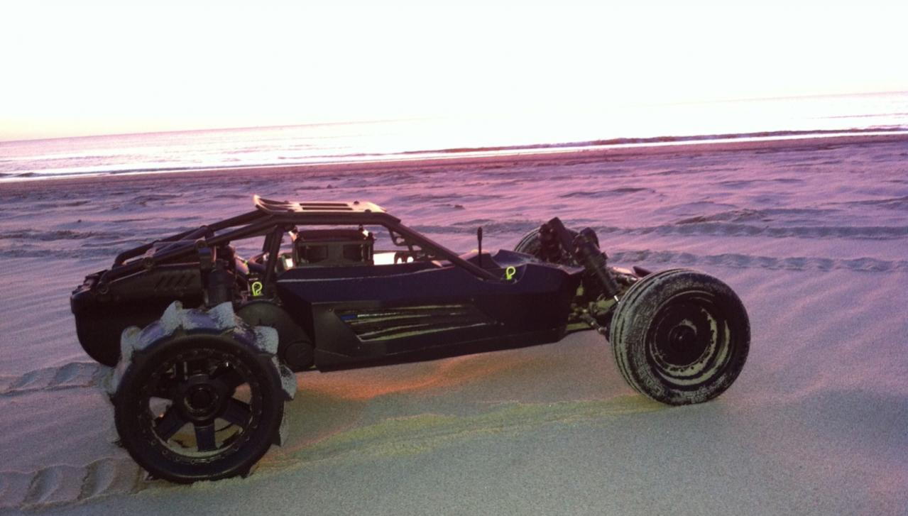
Ran the Kyosho tonight on the beach with paddle tires. Loads are a bit smoother than with the grass sessions. Hit 70 km/h on GPS through the sand. Will edit in some pics when I've rebooted to Win :D.

Code:
ubuntu@ubuntu:~/BLDC$ git clone https://github.com/vedderb/bldc-tool.git bldc-tool
Cloning into 'bldc-tool'...
remote: Counting objects: 620, done.
remote: Total 620 (delta 0), reused 0 (delta 0), pack-reused 620
Receiving objects: 100% (620/620), 1.42 MiB | 1.34 MiB/s, done.
Resolving deltas: 100% (414/414), done.
Checking connectivity... done.
ubuntu@ubuntu:~/BLDC$ cd bldc-tool
ubuntu@ubuntu:~/BLDC/bldc-tool$ qmake -qt=qt5
qmake: could not exec '/usr/lib/x86_64-linux-gnu/qt5/bin/qmake': No such file or directory

My bldc-tool direcotry contains this:
Code:
ubuntu@ubuntu:~/BLDC/bldc-tool$ dir
BLDC_Tool.pro	      mainwindow.h	 mtextedit.h				    rtdatawidget.cpp
datatypes.h	      mainwindow.ui	 packetinterface.cpp			    rtdatawidget.h
digitalfiltering.cpp  mc_configurations  packetinterface.h			    serialization.cpp
digitalfiltering.h    mrichtextedit.cpp  qcustomplot.cpp			    serialization.h
firmwares	      mrichtextedit.h	 qcustomplot.h				    utility.cpp
main.cpp	      mrichtextedit.ui	 qt-linux-opensource-5.0.2-x86-offline.run  utility.h
mainwindow.cpp	      mtextedit.cpp	 README.md
 
vedder said:
With version 4.8 you can connect CSN to the same header and you don't have to modify the servo input. You could also connect CSN to one of the SWD pins and turn off SWD and use the pins as gpio .... For now you could run the server on e.g. a raspberry pi or some other small limux computer.

Hey vedder, it's all looking so good right now I'm going to have to build myself two. I'm putting an email together to a guy I know who can make them locally so wondering how far off is this 4.8 you mention? Is it worth holding the build for a bit or going ahead with the 4.7?

Also, I'm much better with tools than tech, but could I use a windows computer and the windows program marcin developed to both load the programming onto the vesc as well as tune it, or will I need a linux based device to get the program on there to start with? Or is there another non-linux option as I don't have access to a linux system...

Finally, I can't seem to find a schematics for the pcb design, is this derived from the silk screens and overview schematic's pdf or is there a pcb design floating around somewhere?

Anyway, it looks like an incredible esc you have here, I can't wait for it.
 
Dr_T said:
Hi guys, trying to get the BLDC tool running on a linux (ubuntu 14.04 LTS) thumbdrive, following the instructions on vedder.se, but it's not going as planned..., see below. Am I missing some qt5 install? I googled a bit on installing qt5, but I have no idea what I'm doing really. Any help?

Ran the Kyosho tonight on the beach with paddle tires. Loads are a bit smoother than with the grass sessions. Hit 70 km/h on GPS through the sand. Will edit in some pics when I've rebooted to Win :D.

Code:
ubuntu@ubuntu:~/BLDC$ git clone https://github.com/vedderb/bldc-tool.git bldc-tool
Cloning into 'bldc-tool'...
remote: Counting objects: 620, done.
remote: Total 620 (delta 0), reused 0 (delta 0), pack-reused 620
Receiving objects: 100% (620/620), 1.42 MiB | 1.34 MiB/s, done.
Resolving deltas: 100% (414/414), done.
Checking connectivity... done.
ubuntu@ubuntu:~/BLDC$ cd bldc-tool
ubuntu@ubuntu:~/BLDC/bldc-tool$ qmake -qt=qt5
qmake: could not exec '/usr/lib/x86_64-linux-gnu/qt5/bin/qmake': No such file or directory

My bldc-tool direcotry contains this:
Code:
ubuntu@ubuntu:~/BLDC/bldc-tool$ dir
BLDC_Tool.pro	      mainwindow.h	 mtextedit.h				    rtdatawidget.cpp
datatypes.h	      mainwindow.ui	 packetinterface.cpp			    rtdatawidget.h
digitalfiltering.cpp  mc_configurations  packetinterface.h			    serialization.cpp
digitalfiltering.h    mrichtextedit.cpp  qcustomplot.cpp			    serialization.h
firmwares	      mrichtextedit.h	 qcustomplot.h				    utility.cpp
main.cpp	      mrichtextedit.ui	 qt-linux-opensource-5.0.2-x86-offline.run  utility.h
mainwindow.cpp	      mtextedit.cpp	 README.md

Would be nice to see some videos of that :)

I don't know if it will work on a bootable thumb drive since ubuntu is installed in a different way there. If you don't want to make a full install, you are more likely to get it working in a virtual machine. Maybe you can ask Marcin or Jacob to build new versions for you. The latest firmware also has configurable soft low voltage cutoff.

Hey vedder, it's all looking so good right now I'm going to have to build myself two. I'm putting an email together to a guy I know who can make them locally so wondering how far off is this 4.8 you mention? Is it worth holding the build for a bit or going ahead with the 4.7?
I think I will get the PCBs this week, so if I have time and it works well I will upload the new design by the end of the week. I definitely think it is worth waiting.

Also, I'm much better with tools than tech, but could I use a windows computer and the windows program marcin developed to both load the programming onto the vesc as well as tune it, or will I need a linux based device to get the program on there to start with? Or is there another non-linux option as I don't have access to a linux system...
I only run linux on my computers. There are surely other ways to build and upload the firmware, but I can't help with that. Once you have the firmware uploaded you can use Marcins or Jacobs build of BLDC Tool. I can ensure that the easiest way to install the toolchain and build everything to upload the firmware is using ubuntu though.

Finally, I can't seem to find a schematics for the pcb design, is this derived from the silk screens and overview schematic's pdf or is there a pcb design floating around somewhere?
https://github.com/vedderb/bldc-hardware/raw/master/design/BLDC_4.pdf
There is also a link to the whole schematic next to my overview picture.
 
vedder said:
I think I will get the PCBs this week, so if I have time and it works well I will upload the new design by the end of the week. I definitely think it is worth waiting.

I only run linux on my computers. There are surely other ways to build and upload the firmware, but I can't help with that. Once you have the firmware uploaded you can use Marcins or Jacobs build of BLDC Tool. I can ensure that the easiest way to install the toolchain and build everything to upload the firmware is using ubuntu though.

https://github.com/vedderb/bldc-hardware/raw/master/design/BLDC_4.pdf
There is also a link to the whole schematic next to my overview picture.

Excellent, I will wait for the 4.8 then. I'm in Australia, so that makes the boards even easier. Will the BOM and pcb be the same for the 4.8 version? I'm trying to plan ahead and save on shipping time...

I just found the info on the pcb and came to edit my post but was too late, so thanks for the rapid replies! To everyone else, I will most likely have 8 pcb's to get rid of in 1's or 2's very soon.
 
vedder said:
I don't know if it will work on a bootable thumb drive since ubuntu is installed in a different way there. If you don't want to make a full install, you are more likely to get it working in a virtual machine. Maybe you can ask Marcin or Jacob to build new versions for you. The latest firmware also has configurable soft low voltage cutoff.

After some trial-and-error, I at least got the BLDC tool executing now on the thumbdrive, but somehow I still get some socket error preventing the VESC to connect over the USB cable... have to dig into that some more later, would be cool to just have a bootable USB drive with all the stuff needed to configure and update the VESC. For anyone interested, this was the stuff I needed to add to my bootable thumbdrive, made with the Universal-USB-Installer-1.9.6.1, to get the BLDC tool to run:

Code:
sudo apt-get install qt5-qmake
sudo apt-get install libqt5serialport5-dev
sudo apt-get install build-essential g++
sudo apt-get install libudev-dev
sudo apt-get install git

I did already see the advanced tab with the additional settings you added in the BLDC tool :). In case I do get it working tomorrow, what would be a good starting point for the current control gains, the settings from the 1717 config file that comes with the tool? Also, is the latest firmware one of the compiled ones in the firmware directory that is pulled together with the BLDC tool, or do I need to pull and make the firmware as described in your tutorial?

Video of the beach run on 7S:
[youtube]esGs7xEbMKw[/youtube]

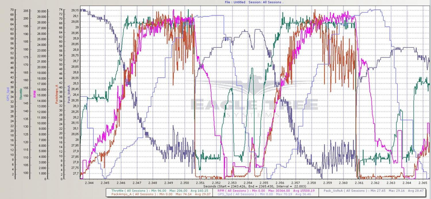
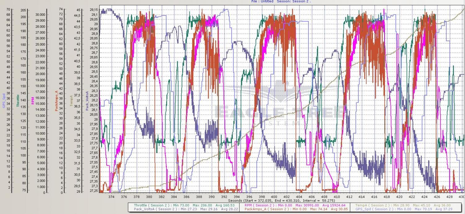
Log data below. Load seems a bit less varying than when running on grass; not sure if that has anythin to do with it, but in 3 packs, I only had 4-5 VESC faults, opposed to 10+ per pack on grass. You can see in the plots the RPM is topping out at about 29-30k (78-80% of unloaded RPM), with Current not hitting the set 90A limit, so I guess that's due to the Current measurement noise and the high back-off gains. Looking forward to testing it with a bit more juice, to see if the 7S batteries can hold 33-35k RPM under load and give some more speed :).

dr_t-albums-kyosho-scorpion-xxl-pt-ii-picture32990-kyo-xxl-beach-6s-7s-1-speed2.jpg


dr_t-albums-kyosho-scorpion-xxl-pt-ii-picture32989-kyo-xxl-beach-6s-7s-1-speed.jpg


dr_t-albums-kyosho-scorpion-xxl-pt-ii-picture32988-kyo-xxl-beach-6s-7s-1-7s.jpg
 
Dr_T said:
After some trial-and-error, I at least got the BLDC tool executing now on the thumbdrive, but somehow I still get some socket error preventing the VESC to connect over the USB cable... have to dig into that some more later, would be cool to just have a bootable USB drive with all the stuff needed to configure and update the VESC. For anyone interested, this was the stuff I needed to add to my bootable thumbdrive, made with the Universal-USB-Installer-1.9.6.1, to get the BLDC tool to run:

Code:
sudo apt-get install qt5-qmake
sudo apt-get install libqt5serialport5-dev
sudo apt-get install build-essential g++
sudo apt-get install libudev-dev
sudo apt-get install git

I did already see the advanced tab with the additional settings you added in the BLDC tool :). In case I do get it working tomorrow, what would be a good starting point for the current control gains, the settings from the 1717 config file that comes with the tool? Also, is the latest firmware one of the compiled ones in the firmware directory that is pulled together with the BLDC tool, or do I need to pull and make the firmware as described in your tutorial?

If you can start BLDC Tool you are very close. In case you haven't added your user to the dialout group you have to start BLDC Tool as root to access the serial port, e.g. using sudo.

The firmware that comes with BLDC Tool is the latest one, so you don't have to build it. You can try a current backoff gain of 0.2 to start with. It could happen that you get more overcurrent faults then. You can also try switching off the abs overcurrent protection completely by setting the limit to more than 160A. The current backoff will still be active, but the risk of frying FETs if the settings are wrong gets higher (e.g. if you have very low backoff gain). If you have reasonable gain you will most likely be fine and if you also have a fuse a fried FET can be replaced without too many other things braking.
 
Hi guys! I've been following this VESC development lately and I think that you really are on to something. I myself am more into ebikes but I think VESC could work really well also in bikes. A colleague of mine at the university bought a couple of VESCs a while back and I'm probably going to test them on my ebike's MAC motor when I've got the time.

First, I would like to know if you think a VESC could be used with a 14S lipo pack charged to 4.15 V per cell, i.e. total of 58,1 V. My motor has a freewheeling cassette so there should not be any regeneration which would increase the voltage over the charged voltage. Except maybe when using the bikes own brakes...

Second, my two cents on how I would like to see the VESC developed further. The software side looks great with the possibilities to write your own programs and communicating with a cell phone app. Eventually this means that you do not need for example a separate display such as the Cycle analyst anymore. I would like to see field oriented control to reduce the motor noise.

On the hardware side, some modularity could be nice. I think a separate brain board containing the microcontroller and the driver circuit would be nice. This could then be attached on top of a power stage in the same manner as shields are attached on top of Arduino. There are a couple of benefits from this. First, you could make power stages for different applications without having to change the whole PCB. There could be one for skates, maybe a little larger one for higher powered ebikes and ever one with several fets in parallel for electric motorcycles (20 kW+). Second, this would probably help separating the high noise power stage from the more sensitive signal circuits. I read you've had problems with the current measurement. With two stacked boards you could lift the signals from the shunts in the power boards straight up to the second board through a nice shielding ground plane and then route them directly to the microcontroller. Same goes for the gate traces, which should not go over the power traces especially in high power applications. Third, the footprint of the ESC could be even smaller in with two stacked PCB:s but of course the height is increased. The power stage should then be designed so that the FETs are all on the bottom side which enables easy cooling for them. Eventually also the gate drive circuit could be separated to its own module which would enable using higher voltages.

I might some day try separating the power stage myself but unfortunately I will not have time for it in the foreseeable future. Maybe next year. Anyway, keep up the good work!
 
I got the BLDC Tool working on my Ubuntu thumbdrive (USB problem was me not reading the turorial properly... just had to change port as described in the tutorial) and I now have FW 1.12 running on my VESC. Hope to do some more test-driving tomorrow, if weather is not too bad.

For a good comparison, I'll use my old Current settings (-90A, 90A, -20A, 90A) first, and put the abs max at 150 A. I'll set the Current back-off gain to .2, as adviced (for my 4 pole inrunner car motor) above.

I saw in the 1717 config file, the “Max ERPM at full brake in CC mode” (motor coil shorting) is at 500, instead of the 1500 in the tutorial, while the "batt min regen" is at -80 A, instead of -20 A. Is there any connection, and could you please explain a bit about the braking and why you chose those values for your 1717 set-up? How is the “Max ERPM at full brake” involved in this (does higher mean stronger braking)? Does an 80 A regen not put a huge stess on small (~5 Ah) RC car batteries (like charging a 5 Ah battery at 16C)? Is there a trade-off between regen braking and "motor coil short" (motor heat?) braking?

Also, is it possible to have the App configuration settings saved in an xml file, like the motor settings, so controller deadband and calibration can be easily reloaded after firmware upgrade?

Thanks!
 
Ran the 1.12 FW with 90 A motor/battery limit and 0.2 Current back-off gain. The lowered back-off gain is very nice: peak Currents now go up to around the set limit (peaked a little over 2.4 kW from batteries) and Current seems to fluctuate less heavy. Motor temps might be a bit lower too, although I only drove 1 pack and it was a bit of a different session than before (bad weather, big crash with some damage), so hard to really compare yet.

Didn't have noticeably more VESC faults than before, but I did have to stop the session early, because the VESC started to cog a bit and then became completetly unsresponsive to throttle input (still had steering, so Tx/Rx were ok; no flashing lights on VESC, just the normal blue led). I kept battery power on, hoping to get some fault readout at home, but it wouldn't even connect to the BLDC Tool anymore: got an "unknown error" trying to connect. After power-down, VESC did connect to BLDC Tool again, but then all faults were gone obviously... Anyone else had this before? I only tested the VESC a bit unloaded now, and everything seems fine and there's no faults showing in terminal, so I'm hoping nothing got damaged.

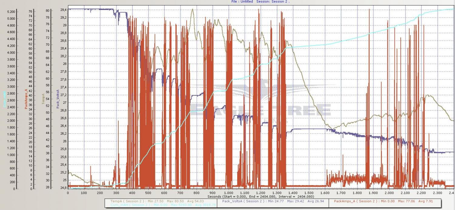
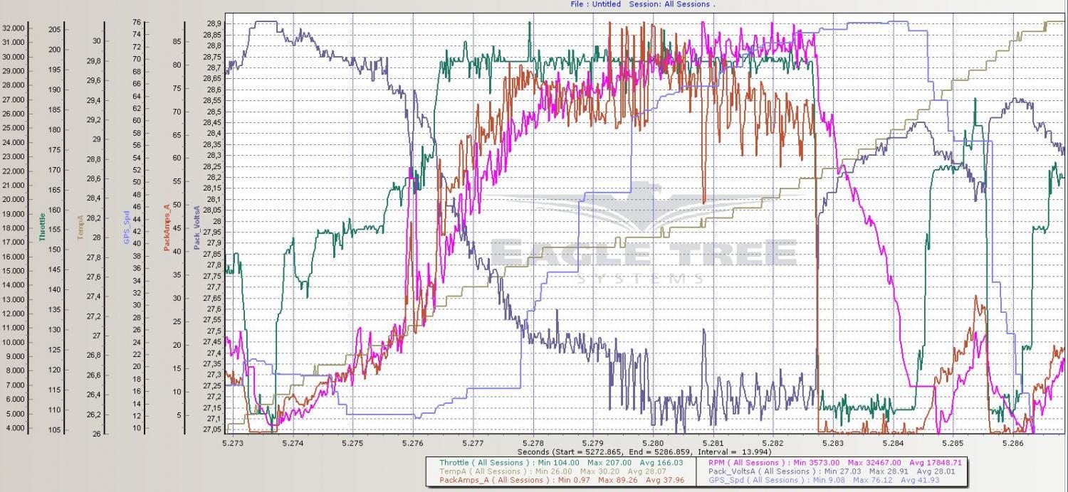
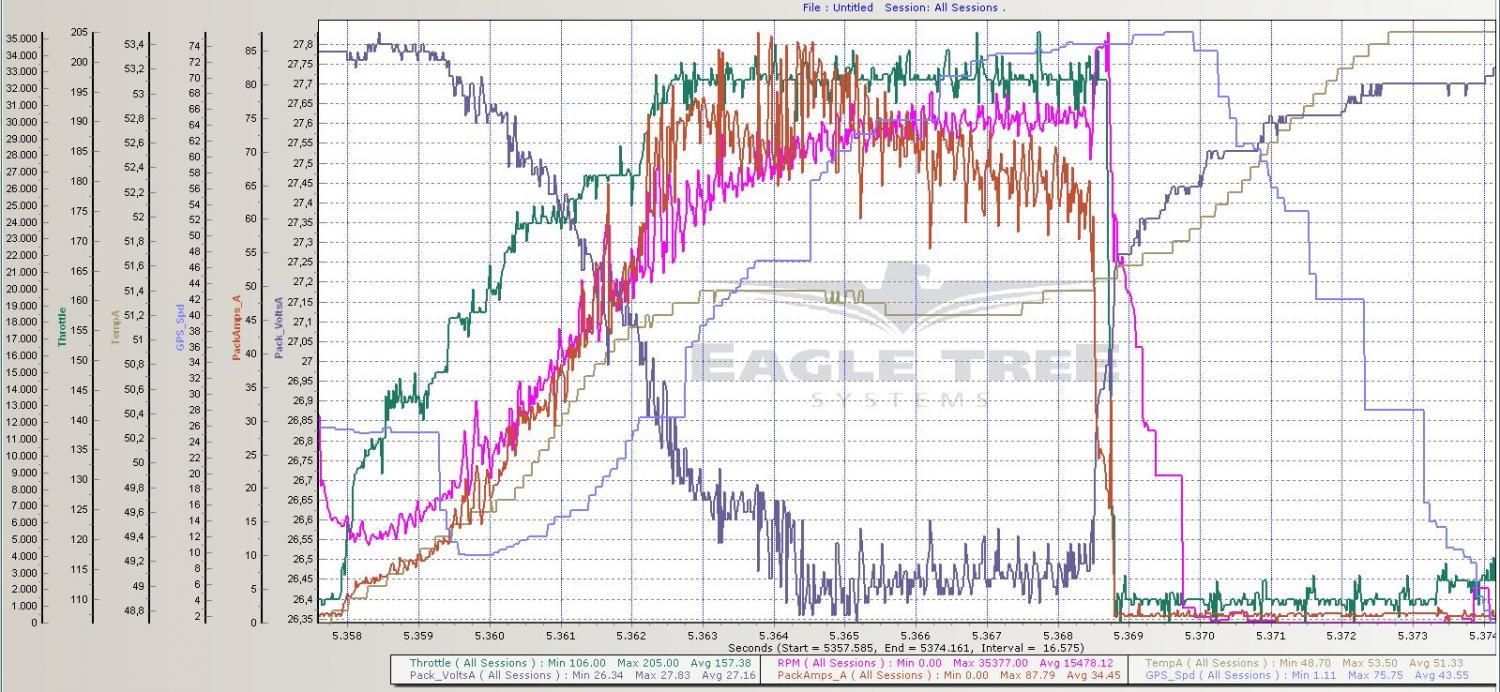
With some tail wind (tail storm :)), I got it up to 76 km/h now, but it seems it's really the load slowing down the motor and not the Current limit. With all the sand flying around, it was hard to see where the car was going at a distance, and I hit a bump which flipped the car while driving flat out; you can see in the log the VESC nicely enforcing the 35500 RPM limit I set, when flying though the air :)

Video:
[youtube]aomjcACfMAk[/youtube]

Full log:
dr_t-albums-kyosho-scorpion-xxl-pt-ii-picture33062-kyo-xxl-beach-7s-2-full.jpg


76 km/h run:
dr_t-albums-kyosho-scorpion-xxl-pt-ii-picture33063-kyo-xxl-beach-7s-2-speed.jpg


~76 km/h crash (note RPM increase when weels lift off):
dr_t-albums-kyosho-scorpion-xxl-pt-ii-picture33064-kyo-xxl-beach-7s-2-speed-crash.jpg
 
Dr_T said:
Ran the 1.12 FW with 90 A motor/battery limit and 0.2 Current back-off gain. The lowered back-off gain is very nice: peak Currents now go up to around the set limit (peaked a little over 2.4 kW from batteries) and Current seems to fluctuate less heavy. Motor temps might be a bit lower too, although I only drove 1 pack and it was a bit of a different session than before (bad weather, big crash with some damage), so hard to really compare yet.

Didn't have noticeably more VESC faults than before, but I did have to stop the session early, because the VESC started to cog a bit and then became completetly unsresponsive to throttle input (still had steering, so Tx/Rx were ok; no flashing lights on VESC, just the normal blue led). I kept battery power on, hoping to get some fault readout at home, but it wouldn't even connect to the BLDC Tool anymore: got an "unknown error" trying to connect. After power-down, VESC did connect to BLDC Tool again, but then all faults were gone obviously... Anyone else had this before? I only tested the VESC a bit unloaded now, and everything seems fine and there's no faults showing in terminal, so I'm hoping nothing got damaged.

With some tail wind (tail storm :)), I got it up to 76 km/h now, but it seems it's really the load slowing down the motor and not the Current limit. With all the sand flying around, it was hard to see where the car was going at a distance, and I hit a bump which flipped the car while driving flat out; you can see in the log the VESC nicely enforcing the 35500 RPM limit I set, when flying though the air :)

Thanks for the update, nice run :) I hope that the car didn't take too much damage.

The fault you got seems like the interrupts were still running, but the OS got into some bad state. This probably happed because of a power dip. The watchdog timer will reset the CPU if the interrupts freeze, but not if only the OS does. I will update that so that the watchdog is reset from a thread that is triggered from an interrupt. On the other hand, power dips like that should not occur, so there is probably something else as well.

At the end of this week I will probably get the new V4.8 boards which I will test with lizards motor since it is the most challenging motor I have at home now. Hopefully some of the problems will be resolved then with these kinds of motors. It is very helpful to get your feedback and getting to test the VESC on more challenging RC motors. The improvements made from this should benefit all kinds of VESC applications.
 
Nice progress with the VESC 4.8 Benjamin, looking forward to seeing more of that!

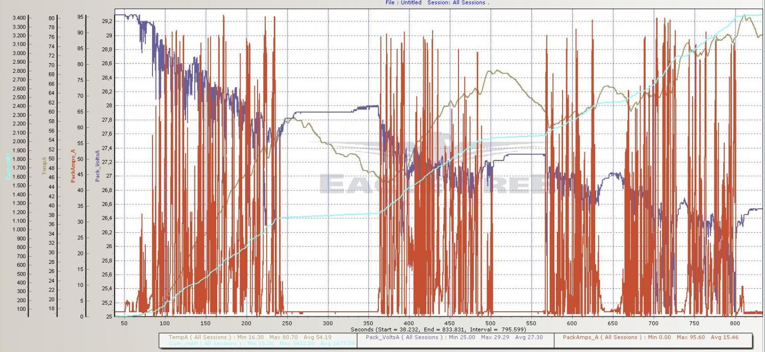
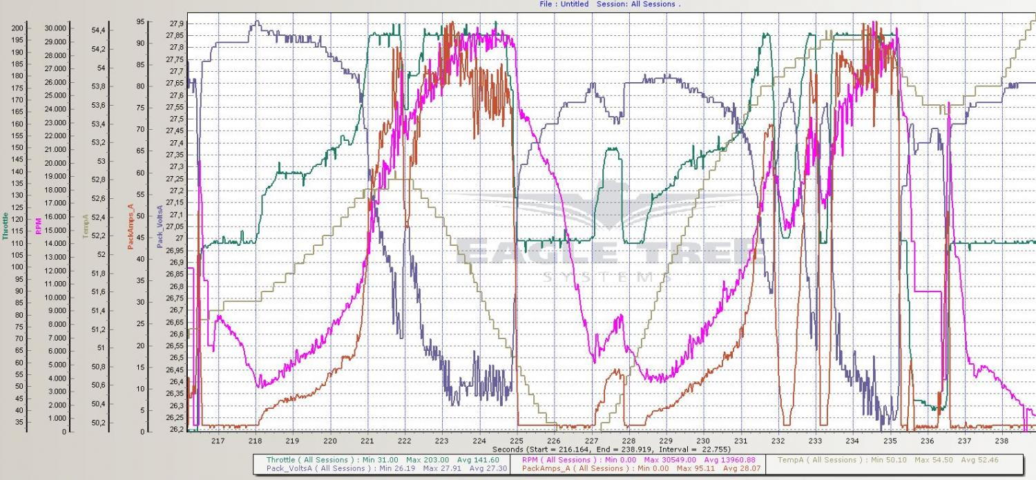
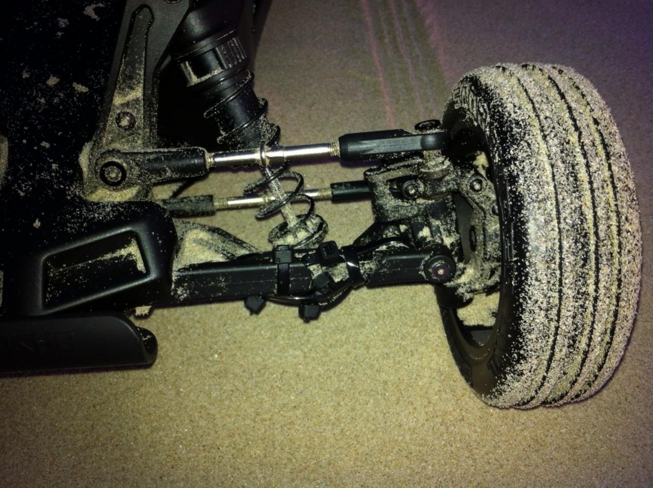
Ziptied the damaged A-arm and ran anoter 7S pack today with motor settings below (100 A motor/battery limits, 0.15 Current back-off gain, 155 A abs limit); I'm really happy with performance now with FW 1.12 and my current settings, drives very well and power is sufficient -more would only have it wheelie and flip-, for now :) (a 100A 10-12S set-up would be pretty awesome though). I did notice some cogging again, like last time before it froze-up. The cogging incidentally happens when giving forward throttle directly after braking to a full stop. I do not recall having that with the earlier firmware versions - but, with changing to FW 1.12, I also changed the l_max_erpm_fbrake, l_max_erpm_fbrake_cc, sl_min_erpm and sl_min_erpm_cycle_int_limit values to the ones you used in the 1717 config file, don't know if that might be related.

Didn't log any over-current faults for the entire pack, but did log 2 DRV faults shown below. They happened during normal, slowish driving (not pushing it, not full throttle), right after a little stop, as I recall under similar conditions as when the freeze-up of the VESC in my previous session occured. Any idea what could be causing those?

Code:
Fault : FAULT_CODE_DRV8302
Current : 106.3
Current filtered : 80.6
Voltage : 25.85
Duty : 0.49
RPM : 23984.2
Tacho : 1282604
Cycles running : 53586
PWM cycles : 1
TIM duty : 3893
TIM val samp : 1943
TIM current samp : 5931
TIM top : 7976
Comm step : 5
Temperature : 23.05

Fault : FAULT_CODE_DRV8302
Current : 112.1
Current filtered : 82.3
Voltage : 25.84
Duty : 0.50
RPM : 26028.6
Tacho : 1304088
Cycles running : 17232
PWM cycles : 1
TIM duty : 3910
TIM val samp : 1949
TIM current samp : 5833
TIM top : 7768
Comm step : 5
Temperature : 26.05

My 4092 Settings:
Code:
<?xml version="1.0" encoding="UTF-8"?>
<MCConfiguration>
    <pwm_mode>1</pwm_mode>
    <comm_mode>0</comm_mode>
    <motor_type>0</motor_type>
    <sensor_mode>0</sensor_mode>
    <l_current_max>100</l_current_max>
    <l_current_min>-100</l_current_min>
    <l_in_current_max>100</l_in_current_max>
    <l_in_current_min>-20</l_in_current_min>
    <l_abs_current_max>155</l_abs_current_max>
    <l_min_erpm>-100000</l_min_erpm>
    <l_max_erpm>100000</l_max_erpm>
    <l_max_erpm_fbrake>300</l_max_erpm_fbrake>
    <l_max_erpm_fbrake_cc>500</l_max_erpm_fbrake_cc>
    <l_min_vin>8</l_min_vin>
    <l_max_vin>50</l_max_vin>
    <l_battery_cut_start>20</l_battery_cut_start>
    <l_battery_cut_end>17</l_battery_cut_end>
    <l_slow_abs_current>1</l_slow_abs_current>
    <l_rpm_lim_neg_torque>1</l_rpm_lim_neg_torque>
    <l_temp_fet_start>80</l_temp_fet_start>
    <l_temp_fet_end>100</l_temp_fet_end>
    <l_temp_motor_start>80</l_temp_motor_start>
    <l_temp_motor_end>100</l_temp_motor_end>
    <l_min_duty>0.005</l_min_duty>
    <l_max_duty>0.95</l_max_duty>
    <sl_min_erpm>100</sl_min_erpm>
    <sl_min_erpm_cycle_int_limit>900</sl_min_erpm_cycle_int_limit>
    <sl_max_fullbreak_current_dir_change>10</sl_max_fullbreak_current_dir_change>
    <sl_cycle_int_limit>65</sl_cycle_int_limit>
    <sl_cycle_int_limit_high_fac>0.5</sl_cycle_int_limit_high_fac>
    <sl_cycle_int_rpm_br>75000</sl_cycle_int_rpm_br>
    <sl_bemf_coupling_k>800</sl_bemf_coupling_k>
    <hall_table_0>-1</hall_table_0>
    <hall_table_1>1</hall_table_1>
    <hall_table_2>3</hall_table_2>
    <hall_table_3>2</hall_table_3>
    <hall_table_4>5</hall_table_4>
    <hall_table_5>6</hall_table_5>
    <hall_table_6>4</hall_table_6>
    <hall_table_7>-1</hall_table_7>
    <hall_sl_erpm>2000</hall_sl_erpm>
    <s_pid_kp>0.0001</s_pid_kp>
    <s_pid_ki>0.002</s_pid_ki>
    <s_pid_kd>0</s_pid_kd>
    <s_pid_min_rpm>900</s_pid_min_rpm>
    <p_pid_kp>0.0001</p_pid_kp>
    <p_pid_ki>0.002</p_pid_ki>
    <p_pid_kd>0</p_pid_kd>
    <cc_startup_boost_duty>0.04</cc_startup_boost_duty>
    <cc_min_current>1</cc_min_current>
    <cc_gain>0.0046</cc_gain>
    <cc_ramp_step_max>0.04</cc_ramp_step_max>
    <m_fault_stop_time_ms>1000</m_fault_stop_time_ms>
    <m_duty_ramp_step>0.02</m_duty_ramp_step>
    <m_duty_ramp_step_rpm_lim>0.0005</m_duty_ramp_step_rpm_lim>
    <m_current_backoff_gain>0.15</m_current_backoff_gain>
    <meta_description><!DOCTYPE HTML PUBLIC "-//W3C//DTD HTML 4.0//EN" "http://www.w3.org/TR/REC-html40/strict.dtd">
<html><head><meta name="qrichtext" content="1" /><style type="text/css">
p, li { white-space: pre-wrap; }
</style></head><body style=" font-family:'Ubuntu'; font-size:11pt; font-weight:400; font-style:normal;">
<p style=" margin-top:0px; margin-bottom:0px; margin-left:0px; margin-right:0px; -qt-block-indent:0; text-indent:0px;">Configuration loaded from the motor controller.</p></body></html></meta_description>
</MCConfiguration>

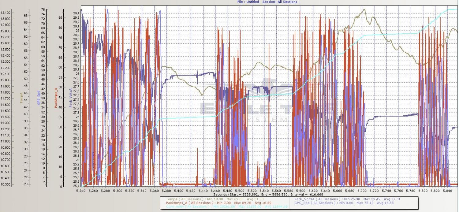
Log:
dr_t-albums-kyosho-scorpion-xxl-pt-ii-picture33108-kyo-xxl-beach-7s-3-full.jpg


Full-throttle snip:
dr_t-albums-kyosho-scorpion-xxl-pt-ii-picture33109-kyo-xxl-beach-7s-3-snip.jpg


dr_t-albums-kyosho-scorpion-xxl-pt-ii-picture33106-photo-1-1.jpg


dr_t-albums-kyosho-scorpion-xxl-pt-ii-picture33107-photo-2-1.jpg
 
Dr_T said:
The cogging incidentally happens when giving forward throttle directly after braking to a full stop. I do not recall having that with the earlier firmware versions - but, with changing to FW 1.12, I also changed the l_max_erpm_fbrake, l_max_erpm_fbrake_cc, sl_min_erpm and sl_min_erpm_cycle_int_limit values to the ones you used in the 1717 config file, don't know if that might be related.

Do you have safe start enabled under within the PPM settings menu? Im curious if maybe you've got 51-52% throttle input and need to trim controller slightly causing safe start to fail due to pulse output being higher then 0 for more the 50pulses

I do know that this is a function checked after breaking and before a start. However could be other issue non related and wanted to see if you have this enabled or not.
 
jamesonotc said:
Do you have safe start enabled under within the PPM settings menu? Im curious if maybe you've got 51-52% throttle input and need to trim controller slightly causing safe start to fail due to pulse output being higher then 0 for more the 50pulses

I do know that this is a function checked after breaking and before a start. However could be other issue non related and wanted to see if you have this enabled or not.

Yes, safe start is/was enabled and I also use the median filter. I've also set pulsewidth range so that I have complete throttle range with my radio and neutral is 50%. What does the safe start do exactly?

Ran one 7S and one 6S pack tonight, same settings as previous post. Had a couple of faults occurring, but also had to disconnect power after another freeze-up where the VESC became unresponsive, so only have the details of one fault (DRV). The faults and freeze-up do mostly seem to occur under similar circumstances, typically directly after a bit of a stop, e.g., after I flipped the car, or after a check-up / cool-down. Also had sam type of occasional cogging as described in previous post.

At first glance, the three DRV faults I have details on, all seem to have in common that it happens at around 50% duty cycle and at comm. step 5:

Code:
The following faults were registered since start:

Fault            : FAULT_CODE_DRV8302
Current          : 109.8
Current filtered : 89.0
Voltage          : 21.78
Duty             : 0.51
RPM              : 21819.4
Tacho            : 314645
Cycles running   : 18322
PWM cycles       : 1
TIM duty         : 3921
TIM val samp     : 1956
TIM current samp : 5771
TIM top          : 7630
Comm step        : 5
Temperature      : 30.78

Didn't run through logdata yet, but thought I'd put this up here already - hope this is still usefull, even with VESC 4.8 on the way.
 
I am a bit lost with the versions of the VESC.
I am about to buy PCBs for the 4.7 version.

Is there a changelog of changes between versions ?
Is the BOM specific for a given version ?
 
akiraEC said:
I am a bit lost with the versions of the VESC.
I am about to buy PCBs for the 4.7 version.

Is there a changelog of changes between versions ?
Is the BOM specific for a given version ?

You might want to wait for VESC 4.8.

Version of BOM and vesc design files at github matches and is currently at 4.7,
but 4.8 seems to be around the corner (few weeks?)
 
Thank you Vedder again for developing the VESC for us!

I'm also curious on what the major changes and improvements are between 4.7 and 4.8?

I do not have the skill to SMB solder (but threatening to learn!). I am trying to decide if getting two of the 4.8 VESC's from onloop/enertion makes sense? I could re-use my existing 4.7 VESC's in other projects/boards or keep as spares. I'm mostly curious about what improvements are applicable to e-boards. >200kv on 12s perhaps?

Because of Dr T - i did get an eagletree for my upcoming build - love the info/data it lets you log!!
 
sl33py said:
Because of Dr T - i did get an eagletree for my upcoming build - love the info/data it lets you log!!

Cool! :)

If you're interested in adding a cheap GPS to the logger, here's some info: http://www.rcgroups.com/forums/showthread.php?t=1874964. Beware though that some of the really cheap modules from China, like the ones I tried, seem have some issues with the EEPROMs, causing them to lose configuration settings when power is lost.
 
Hey short question,
is it possible to harm the VESC if I connected receiver wires wrong?
I connect like this:
RX(arduino) -to- VESC
gnd ------------------- gnd
signal ---------------- +(5v?)
5v pin ----------------- signal
could that cause damage to my vesc?-.-
or should the signal pin can handle 5volts? the arduino was broken just changed it

see what happens https://vid.me/JkB1
 
jacobbloy said:
bldc tool updated to FW1.12 for windows and mac.
Thank you, great work.

I have sourced an old v4.0 hardware and playing with it now. Motor in question is Turnigy Rotomax 150cc, which has somewhat troublesome low inductance (17μH). What I have noticed so far:
* Motor is spinning no-load after parameter detection, but start from zero is not that great.
* There is quite a lot of noise coming from HF injection at low speeds, much more than from $5 sensorless controller. But of course loaded start should be much better.
* FETs do get warm (40C) after few minutes of no-load 50% operation.
* Currently testing it with 10K pot connected to ADC, and it is not very stable at lower speeds, picks up noise from somewhere. Have not investigated further yet.
* I do get various issues with USB connection: sometimes it looses connection and, even though virtual COM port seems to be operating fine, BLDC tool does not recognize the device. Re-plugging does not help, I have to cycle the power and reconnect USB afterwards.

Overall, happy so far. Looking forward to FOC implementation, that could be a killer product.

Will try it on MXUS 3000W v2 hub in few days.
 
chinyp said:
Where can I buy this VESC? Omg please take my money :mrgreen:
Someone tell me please....


I have VESC available.

You can see this link for details.
https://endless-sphere.com/forums/viewtopic.php?f=31&t=71226&start=50

REV 4.7 Boards.

I will be order rev 4.8 boards immediately following vedders release once 4.8 BOM is available.
https://github.com/vedderb/bldc-hardware/blob/master/design/BLDC4.8_BOM.ods
 
Hi everybody,

how can I read out the log-data (current, voltage temp... ) from the VESC? Is there a possibility to get the data with out connecting a computer during the test drive?
I'm using the BLDC tool from Marcin for Windows.

Thx for for reply :D
 
vedder said:
sweet video. How do you get all this telemetry information ? Are you using an eagletree logger? thanks!
Damn good work Vedder!

How do you connect the ESC to the computer? Is that wireless?


I have connected the ESC to my laptop with an USB cable. The video overlay is done in real time with a Qt application that handles sound synchronization and overlay and opencv to capture and compress the video in real time. This is done with 4 separate threads to keep it smooth and synchronized. I have uploaded the full source code for that application here:
https://github.com/vedderb/bldc-logger
There are also some instructions if you would like to try it yourself.

Yes very good work! I think its ready for group buy. This is probably more testing than the chinese companies has ever done :)
Thanks! I would like to order one more version of the PCB though, because I made a small adjustment to one of the current shunt paths to get better current readings. I will also send my prototype to Austin and let him test it.

Here is a past reply from vedder discussing data logging
 
Back
Top