2008 CRF250R - QS138v3 70H - ANT - Sanyo UR18650-RX 20s20p - Votol EM260

It sounds like you have too soft rear spring with that 24mm static sag, do you know how much preload?
But the shock likely needs a rebuild too ;)
I think I have changed springs 4 times, and it is still too soft..
I haven't measured the preload on the spring, just the sags. I agree that it likely needs a rebuild, because pretty much any issue in there will also manifest as it being too soft, like not enough pressure, not enough damping etc. I have another one ordered that should be coming to me soon, I'll see how it compares and will have a spare to give out for service so that I have something to ride on.

speaking of...
1747068213777.png

I still can't get over how nice it is to jump off of my commuter bike and onto this thing. I rotated the bars to the +2 position (to the front), let out a bit of pressure from the front tyre and added half a turn of preload in the rear. It's not exactly the most comfortable (as I'd prefer the bars neutral but mounted 2cm forward) but at least it turns now.
 
Actually I have a sneaking suspicion the rear shock might have been lowered. That would explain surprisingly low feel, too slack head angle and my other issues. Stay tuned for updates once I receive the other shock.
 
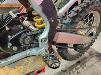
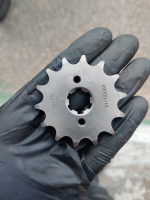
New shock should be here tomorrow, fingers crossed. In the meantime, I did some fitment tests and managed to get 15T in:

1747167588286.png

I think 16T could maybe barely fit with enough slack, but I might just wait for the chain to lengthen, lol. The new sprocket is a cheap variety, but with a decent fitment on the shaft. Not as good as JT or AFAM, but not as bad as what came with the motor. I was more surprised about the locking plate - the plate I used with the AFAM 14T was so thick that it wedged really solid in the shaft slot. That meant that when i tightened the sprocket, there was no play at all. This one is so thin that it freely fits in the slot, resulting in quite a lot of play.

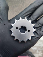
I think it might be for the better, since this is how the sprocket I took off looked like:

1747167812793.png

1747167840656.png

Not horrible, but clearly showing signs of uneven wear. As far as I understand it, the play should allow the sprocket to self-center. I did put everything together and went for a quick spin, but it was raining and I wasn't going to test the WOT pull. It feels just as strong as before, maybe a tad more twitchy from standstill, and seemingly much quieter.

For the people not up to date, this gearing change means going down from quite absurd 10.07 to a more standard, but still quite short 9.40.
 
Last edited:
What rear sprocket are you running ? I assume the ratio you gave are including the rear wheel ? Unless you have a 141t rear sprocket ? 😳
 
I managed to sniff out the Votol protocol on the PC side (PC-usb adapter) as well as the hardware side (usb adapter-votol). Confirmed the data format used and CAN bus transfers. Parts to interface with it directly should arrive today. I also ordered a couple of display options, because I decided I want to have some onboard monitoring after all. We'll see how the programming goes and how it looks IRL
Looking in depth to your build thread, do you mean you managed to find a way to interface with Votol controllers?
That's interesting as I was looking for hacking friendly controllers available.
My first choice was getting Electro&Co Zapper controller as it is using VESC but it is not available yet for purchase.
Then, I came across discussions on this forum about 3Shul being VESC friendly, but hardware doesn't seem that great given several reports of overheating.
Another option but not sure if hackable though is X9 controller which seems to use VESC too.
Finally I also considered Fardriver as I've seen github project which seems to have reversed engineered communication protocol, but not sure what can be done.
 
Last edited:
Looking in depth to your build thread, do you mean you managed to find a way to interface with Votol controllers?
That's interesting as I was looking for hacking friendly controllers available.
"Hacking" and "interfacing" are sort of different in my book. I can talk to it enough to get the rudimentary runtime data over CAN. I know that at least a few people were also able to put new settings on it without using the crappy official app.

We do know that it uses a very common STM chip, though. There's firmware around and you can ST-link to it directly. I tried taking a stab at decompiling the firmware but it's veeeery unreadable, as you'd expect from a freestanding embedded implementation. Having open source firmware for them would be killer and would mean no need for time-consuming reversing of the comms protocols.

Incidentally I think I might have an update to the swingarm/shock/height situation even before the new shock arrives. I was damn sure the new swingarm I bought will "just fit", and when it had a different chain guide mounting point, i just handwaved it away. Well, turns out there might have been more changes in the swingarms, especially if by accident I got one from a 450. They will generally bolt together fine, but there might be an offset in the shock mounting eye causing the wheel resting location to be whack. The easiest way to check would be to measure it against the old swingarm, either on the bike or off, and see if there's any difference. If there is, and if the shock(s) are fine, I might need to either:

- go back to the original swingarm, fixing the adjuster
- buy a new swingarm but one that actually fits
- try to source a connecting link for the new swingarm which might be a tad different length

It's kinda crazy that those parts might almost fit, but not quite, to the point where it's really not clear if they do. If the rear does indeed sit lower than it should, I don't think it's more than 20-25mm of a difference, but that's of course enough to cause significant weight distribution issues.
 
Sooo I gathered all serial numbers for all swingarms, rockers and links from all years spanning 2004-2008, both for 250 and 450. I definitely have a connecting link from a 250, with 132mm length. The new swingarm seems to be exactly the same mounting-holes-wise as the old one. and yet I measure 31-32 degrees fork angle right now, while it should be 27.50 :/

Shock should be here tomorrow.
 
Did a short test ride with 15T today, but i had issues with power cutting out. Immediately after going back home, i found a loose negative connector. Oh well...

It doesn't seem to be too bad on climbs, anyway, still has plenty of pull. I still need to do another round of programming, but it turns out the only Windows laptop i have laying around is a 32-bit machine, and the Votol tool is 64-bit. Sigh.
 
Not good. The new shock was from a 450, and it's shorter:

shock_450.jpeg

It also has severe corrosion on the shaft and is overall in rough shape - although the compression adjuster looks way better than mine. I guess it'll become mostly a parts donor.

To that end, I've ordered... two more shocks. My matrix of all serial numbers of all shocks between all years and 250/450 is getting filled, and I'm getting a better idea for the suspension/geometry differences between them. I will freaking get it to ride right, somehow, eventually. Good news is that the parts for used Hondas are reasonably cheap. I'm also planning to use the "parts" shocks for practice. I kinda always wanted to learn servicing suspension, but the prospect of doing it with my own good set wasn't very enticing. With a shock that's effectively scrap, i get a safe pass. Plus, I will get a couple different spring options paying the price of a new spring for each shock, roughly.

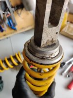
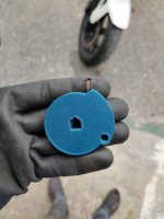
A small bonus - since I took my current shock off, I also managed to snap this pic:

250_shock_circlip.jpeg

I have no idea how I missed it before, but I can only be glad that this thing didn't collapse on me during riding. Homegrown mechanics are the absolute worst.
 
While gathering all the spare parts to rebuild an entire KTM 85 SX front end to fit on a Sur-Ron, I was constantly referring to KTM parts references, which has been incredibly helpful.

I guess this is the clear advantage over Chinese manufacturers: you have access to all the parts references, and they are usually easy to find at a good price, considering wide availability of aftermarket parts ..This is really a great time for DIY enthusiasts to rebuild things.
If it weren't for the road-legal issues with dirt bikes, I would probably have done a similar CRF conversion.

Looking forward to see how the bike behave once build is fully completed.
 
1747678820553.png

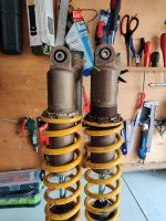
I think this is the one. It's exactly as long as the one that came with my bike, but seems properly serviced and with appropriate pressure. I set the static sag to 18mm and it immediately rides much better now, almost no kicking from the rear, all of that from middle-of-the-road settings, which to me is a good indication I'm very close with the setup. All that's left is playing with the settings a bit, and then i can decide which one to give out for service.

The one with the white spring is another shorter one from 450. That one is actually damaged, so i might use it as a first practice piece - and the spring seems extra stiff, so that's good to have in my arsenal.

I also reprogrammed the controller after putting 15T in:

Phase current: 8600 -> 9000
rate of rise: 60 -> 120
busbar: 100A -> 150A
sport busbar: 200A -> 250A
low gear speed -> 50% -> 40%
low gear current -> 100% -> 50%
mid gear current -> 100% -> 80%

I did some "datalogging" by the means of screen recording my phone with the BMS app open. The readings are very close to expected, with a maximum of 17kW I was able to get on 40% battery left. I also recorded the cell screen by accident, which at first I was very annoyed with, but then I realized i can actually look at how much the cells are sagging under load, which is a useful indication.

As a matter of fact, here's the power/voltage video:


It's dropping from 72V to 64.3V, or 0.39V per cell. I don't know how bad it is, seems like quite a lot.

And here's the individual cells:


One more thing that came to mind, related to the power modes; I'm pretty sure either my switch or the wire from mode select is broken. At first I thought the surging in L mode was caused by improper tuning, but now I'm pretty sure it's actually getting out from L into the default, much faster M. If I had my screen done, I'd see that immediately, but alas... Time seems scarce these days. I observed no discernible power/current difference between the modes, anyway, they just seem to limit the RPM.
 
Last edited:
The first thing I can say from the preview frame in your post of that second video (haven't watched the actual video) is that the cells are mismatched; they don't all have the same properties (resistance, capacity, etc), whcih makes them all different voltages. That means that none of them will perform the same as each other, and some wil sag more than others.

Uusally the ones already lower in voltage (at middle to end of charge) will sag more than the rest, but if the pack is charged (but not yet balanced to be the same voltage) then the ones that are already full there will be the less-capable cells and will sag more than the tohers and empty faster.

Many times an unbalanced pack is also made of less than perfect cells so they already have higher internal resistance than they should (especially if they were used, or old, or both), and so will overall sag more than perfect cells.

If they are all new cells, then they aren't the best ones out there, and they weren't matched by the cell maker or the pack builder (a time consuming and expensive process especially for the builder as it "wastes" a lot of cells that can't be used with other cells because they aren't identical).

And if they are all new cells, then they aren't the right ones for the application if they have more voltage sag than you want, as the cels are higher resistance than you need for the application.

For some examples of how much sag there is on various cells, you can look at testing data here on ES by Pajda, etc., and you can also look at places like lygte-info.dk where there are numerous tests of various cells at various rates and charts to visualize that sag under load for them.
 
The first thing I can say from the preview frame in your post of that second video (haven't watched the actual video) is that the cells are mismatched; they don't all have the same properties (resistance, capacity, etc), whcih makes them all different voltages. That means that none of them will perform the same as each other, and some wil sag more than others.
While you're likely right about the cells not being of super high quality, the preview frame shows the battery under load. Right at the start of the test, the Vdiff was 0.007V. The absolute highest during load was 0.084V; that's at the time when they're sagging by average of ~0.35V. The "lowest" and "highest" group indications jump around through various groups as well.

What would be the min-max group voltage diff at full load you'd expect from a "balanced" pack?

I'm staying well within the manufacturers specifications at 12.5A / cell peak discharge. I expect the battery lifetime will shorten considerably if that number goes up, but I'm not that concerned about ultimate longevity of it; especially because I do have some plans for replacement.
 
While you're likely right about the cells not being of super high quality, the preview frame shows the battery under load. Right at the start of the test, the Vdiff was 0.007V. The absolute highest during load was 0.084V; that's at the time when they're sagging by average of ~0.35V.

That's probably not too bad, if the load was relatively high at that point.

The "lowest" and "highest" group indications jump around through various groups as well.
If that means that which groups are higher or lower in voltage relative to others keeps changing, that probably means the device doing the measuring is not well-designed or made, or that it is measuring in some way that is discontinuous and not sampling all groups at the same time. For instance, if it samples the most negative group, then the next, then the next, then the next, the load when riding will vary a fair bit from moment to moment and so the sampled voltages aren't actually all under the same load.

So in that event your cells could be perfectly matched and exactly equal all the time, but the display wouldn't show that unless you used a steady constant DC load on the pack to do the testing.

Even then, it might stil show a sequential drop from first cell to last cell measured if the time between samplings is long enough and the load is high enough to cause enough voltage drop in the pack over that time.


What would be the min-max group voltage diff at full load you'd expect from a "balanced" pack?
Keep in mind that "balanced" only means the cells are at the same voltage at whatever point in the SoC curve you're measuring.

The worst-case Vdelta would depend on the actual cell characteristics.

"Matched" cells should give "zero" Vdelta under any conditions the cells were designed to handle if they are identical properties (matched).

Hardly anything is really matched, so in practice that's a theoretical goal. ;)

Realistically, sometimes you can get limited groups of matched cells, usually from used EV modules and the like, since they are usually using higher grade cells and higher capability cells and probably performing matching of the cells before building their modules and packs with them.

So...my ancient EIG cells (of EV origin, though I don't know the details), last time I tested them a few years ago, under a static ~2C load (they're capable of 5C as designed, but are about a decade and a half old) were all at a zero Vdelta for the two decimal places I can measure with my Fluke 77-III multimeter, one cell at a time while under that static load. So while they sag quite a bit compared to how they originally performed, they do so together, at least. :lol: I don't have the stuff I did the load test with anymore, though (a bunch of old stove, oven, and other heating elements all paralelled).
 
That's probably not too bad, if the load was relatively high at that point.
Yeah, that was at 17kW, or 12.5A per cell, or ~6C.

"Matched" cells should give "zero" Vdelta under any conditions the cells were designed to handle if they are identical properties (matched).
Hmm, maybe in a lab. But in a battery even if the cells themselves were identical, the welds, connection lengths etc. won't be. And even if the cells all heat up the same, I'd expect a thermal gradient where the innermost cells will run hotter than the ones touching the much colder enclosure, resulting in a change of resistance and thus voltage.

So, I feel it's important to quantify that drift. You're saying you got < 0.01V (or even <0.005V) min-max group diff at a static 2C; that's indeed at least an order of magnitude better than what I'm seeing, even considering much higher loads and the fact I was riding a very much non constant draw vehicle at the time. I'll definitely keep an eye out on how they behave and whether the cells start exhibiting some persisten anomalies, but in the meantime while the battery is operational, I don't necessarily think I can do much about the values I'm seeing.

Still, it's going to be very interesting to compare to... ah, I'm getting ahead of myself ;). Soon.
 
Small update: with the 15T sprocket, I just got back home after 40km ride with 39Ah used, and the battery at 64V - in other words, 0%. So there seems to be a small but meaningful range improvement, despite the bike having more power now.

As for power, I found myself not using S mode at all now that I have around 11kW in modes M and H. L seems to be malfunctioning and is getting in and out of it, which I attribute to a wiring issue. 11kW seems more than enough for twisty, low speed trail riding as well as some open acceleration, and I appreciate the now much better suspension much more; although there's still some improvement to the front-back weight balance to be had.

Frankly, at this point I'm attributing the overall front feel to excessive spring preload, which is unfortunately not adjustable. I need to measure how much the stock setup preloads the springs. They rest on a collar that sits on a ring that sits in a groove machined in the cartridge body. Seems easy enough to put it in a lathe and machine a new groove, move the ring up and reduce the preload?
 
Back
Top