300A bldc esc, mosfets ringing, help

Mihai_F, do you have a schematic for your design?

Read this before deciding to switch devices as fast as possible. Choosing device switching time is about balance.

https://toshiba-semicon-storage.com/info/docget.jsp?did=59464
 
zombiess said:
Mihai_F, do you have a schematic for your design?

Read this before deciding to switch devices as fast as possible. Choosing device switching time is about balance.

https://toshiba-semicon-storage.com/info/docget.jsp?did=59464

Well i had 2 attempts at making a complete schematic and to this day i did not finished it, i have bits an pieces here and there, i personally find it easier to work from the layout, that way i know precisely what goes where, so then i did not put any more effort in to finishing the schematic. I can sow you the layouts.

Yes, about application notes, i read that and may others a while ago, and every now and the i read therm again, and every time i understand more deeply the principles, they are very useful, but only experience make it sink in, it is like learning to fly, you read the theory about it, it makes perfect sense, but if you do not practice you can't learn it....

Now about fast switching, i had a funny (to me atleast) experience wile ago, it might be off topic, but it might be helpful to someone someday. After i completed my ESC v1.2 for the plane, i decided to make a battery charger for my plane battery (Li-Po 22s 60Ah), the design was a simple buck converter (not going to talk about BMS ), a high side switch (FET and the gate driver ic) a freewheeling shotky diode a big coil and a cap, then i decided to switch that fet on and off at 50ns for low loses and small heat sink. All worked great, i was running the buck converter at 1Kw (92v at 11A) thru resistive load (please note resistive) 2 clothes irons and 2 hair dryers :mrgreen: , there was a bit of overshoot and ringing at the switching node, but nothing horrible. Then i decided to connect the battery and start testing how would it charge, i was very confident that it would work perfect, but it was not. The circuit when connected to the battery and powered, once current started to go over 1A my picoscope device would lose connection with the PC, the PC monitor would display some strange horizontal lines and shortly after that the micro controllers that controlled the buck and the LCD would reset. I started investigating, i found that at switching node i had an 100v overshoot ,Vds rise over 200v in 40ns followed by some crazy ringing, FET Vds was 250v. For about a month i bashed my had and i could not explain why with resistors workend and with battery not, then one day in the bathroom (great aha moments and ideas had came in the bathroom...:D ) it dawned on me, the battery is not just resistive is also inductive, and then i was thinking at those 200v in 40ns. Man i made a wide band radio jammer :oops: , the EMI that it created was enough to disturb USB connection with PC and a display connection with PC. The solution was simple and elegant slow down the switching, so from 40ns i went down to 300ns and every thing was nice and ringing free, and i could charge my battery at 1kw without disrupting every electronic device in the neighborhood. Most probably a noob mistake, but it was a gerat learing experience for me.
 
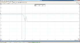
this is on high side fet-s, but not all the time, in 64 captures about 1/4 of them every now and then are like this, the rest of them are without that pulse after turnoff, could it be self turn on or what is that? i read a few suggested papers (parasitic turn on, dv/dt, ect.) and i suspect gate resistor (47r) might be to high value, and that can cause self turn on..
HS fet-s turnoff 1.jpg
 
Have you got a gate trace to go with this? Parasitic turn on should be visible from the gate signals.

I had something similar to this when I was writing my code for BLDC... It was the result of the timing between commutation and pwm and i got partial pulses occasionally.

How much dead time are you running? With the newer FETs, parasitic turn on would be quite unlikely except that with the slow gate resistor it might not be properly discharging the gate in time for the next FET turning on. Slow switching requires more dead time.
 
mxlemming said:
Have you got a gate trace to go with this? Parasitic turn on should be visible from the gate signals.

I had something similar to this when I was writing my code for BLDC... It was the result of the timing between commutation and pwm and i got partial pulses occasionally.

How much dead time are you running? With the newer FETs, parasitic turn on would be quite unlikely except that with the slow gate resistor it might not be properly discharging the gate in time for the next FET turning on. Slow switching requires more dead time.
No gate traces, i have to wait for some parts.
Is dead time necesarly if there is NO complementary switching, i had 700ns at some point, but also none, and it worked both ways...., my switching scheme is bloc commutation with pwm on low side, with NO complementary switching.
 
Mihai_F said:
mxlemming said:
Have you got a gate trace to go with this? Parasitic turn on should be visible from the gate signals.

I had something similar to this when I was writing my code for BLDC... It was the result of the timing between commutation and pwm and i got partial pulses occasionally.

How much dead time are you running? With the newer FETs, parasitic turn on would be quite unlikely except that with the slow gate resistor it might not be properly discharging the gate in time for the next FET turning on. Slow switching requires more dead time.
No gate traces, i have to wait for some parts.
Is dead time necesarly if there is NO complementary switching, i had 700ns at some point, but also none, and it worked both ways...., my switching scheme is bloc commutation with pwm on low side, with NO complementary switching.

Dead time has less meaning in that case. You couldn't even implement it if you tried. However, you will have to take care that when you change between the hall states and thus high being pwm'd and low clamping that you insert dead time of sorts... Or if switching to tri state you might get odd effects in the transition. Is this one in 4 the one at the end of the hall sequence?

It makes parasitic turn on with those FETs quite unlikely. But there's a lot of inductance kicking around your circuit so it's possible.
 
mxlemming said:
However, you will have to take care that when you change between the hall states and thus high being pwm'd and low clamping that you insert dead time of sorts..... ... Is this one in 4 the one at the end of the hall sequence?
I did not fully understand that “is this the on in 4... “
And can you elaborate a bit on the first part the one with changin hall states, pwm, and clamping
 
Sorry, fat fingers.

I meant is the one in four out of 64 you mentioned a few posts ago corresponding to the changes in the hall sensors causing a pwm commutation?
 
Well in that trace, the motor was running WOT at 3000rpm, at that speed commutation time is 166us, pwm is not present since duty cycle is 100%, hence wot, my scope was set for 64 captures and every now and then, completely random about 10 to 14 shots out of 64 but not in a order, they are random, i get a pluses like that, so it is not related to the 6 hall states, i captured an a single shot 12 commutations, on some shots there are pulses on some there are not, it is just random. The low side also has this behaviour at turn off (not that often like HS) but is follwed by bad ringing see the first shots (the one with 100r gate r. ) in the topic. PWM pulse over a comutation pulse i know how it looks, it is not that. I think it is related to gate resistence efect on controlling the fet, with 15r there were no pulses like that, with 100r all switchings had that pulse, with 47r only some at random intervals, now il try 22r and see how it goes.
 
Really does sound like the issue is with the resistor value then.

Things are never truly random. In this case it's probably related to the amount of current flowing at switch time, and the parasitic inductances and possibly the body diode causing gate bounce.

You could try adding a pull down side between gate and gate driver, that way it turns off hard but turns on much more gently.

Or add a capacitor in parallel with your resistor so that it pulls hard against high frequency changes?

Or:

It could be that the low side FET isn't turning on soon enough at the commutation on another switch node which forces more current back through the third phase and that pushes up against the body diode.

I saw all kinds of weird crap on the switch nodes when i was running bldc and it was all related to commutation.
 
Back
Top