Adding MOSFET-s to get more power

AmpAnthony

1 µW
Joined
Jun 29, 2020
Messages
4
Hi!
I did research in this forum and others, seems it can be possible to add parallel MOSFET-s to controller, to increase current capability.
I red that capacitances of parallel FET-s can be problem, they could not switch correctly and make short circuit (when + and - FET-s are on at the same time). It helps if we add resistors to each gate (30-100ohm) but this will make them slower to switch.
I have a 500W brushless controller (low cost) which I would like to make more powerful by adding FET-s. I will use NCEP01T13A MOSFET-s. Don`t look at FET-s :shock: - connected just for testing right now.


Controller seems to already have 100ohm resistor for FET


1. So my question is, what problems can I expect with paralleling MOSFET-s?
2. What size resistors to use?
3. Is correct way to connect parallel MOSFET gate resistors into original gate connection point?
4. Can adding resistance to gate make is so slow that I will have short circuit (- and + turned on same time)?
5. How many parallel MOSFET-s is possible?

Idea:


Let`s not discuss is this acitivity reasonable vs buying more powerful controller, just learning project :) current shunt will be modified, FET-s will have copper cables for power and heatsinks
 
As you note, there have been threads about this before, which present some of the problems, and may have some solutions...but it takes a redesign of the controller and PCB to do what you want to do really effectively.

Problems I can think of off the top of my head, in no particular order:

gate-drive current (which you may be able to fix by changing the gate drivers for better ones, but may have to redesign the PCB to fit them)

heat removal for the new FETs *without affecting that of the originals*; you can't just add them to the old FET heatsink, or you are just adding their heatload to that of the old ones, increasing the problems already present there.

capacitance in the drive and power traces to the new FETs which affects turn on and off time and timing

timing of signals, which must be identical to all FETs on a phase bridge half.

matching resistance of the FETs so they actually share current well enough to help.


There's probably other issues I haven't thought of above.

So...you can try the experiment, if you have the budget and time, but you may end up having to replace the controller if something goes wrong and blows the FETs / gate drivers / etc up, which often leaves the controller unrepairable.
 
Tommm said:
Simpler to replace them, has been done many times.
This ^

There are many high performance mosfets available that shit all over the garbage that come in cheap controllers. If you really want to spend money upgrading your controller, then that is the neatest way to do it.

Obviously, you'll need to ensure the traces and wiring and current shunts are capable of running increased current too.

You plan to add NCEP01T13A, but these are 4.6mOhm Rds. You could use IPP023N10N5, which are 2.3mOhm. TBH, I haven't compared any other specs, but I'd be willing to bet the Infineon is better in every way (and more expensive).
https://www.infineon.com/cms/en/product/power/mosfet/12v-300v-n-channel-power-mosfet/ipp023n10n5/

A note on adding more mosfets (instead of replacing): If the added mosfets have lower Rds, then they will dissipate proportionally more power than the factory mosfets. Consider, since they are in parallel, they must share the same voltage drop. Hence the lower resistance units will carry proportionally more current (V=IR). And power is current squared x resistance. So the end effect is the lower resistance mosfets dissipate proportionally more power. Not optimal performance when some mosfets run hotter than others.
 
Installing more powerful mosfets I agree, is best way to go. Thing is, I just have NCEP01T13A around for no cost. I will use only one type of mosfet so Rds should be the same and share load equally. For higher current, I will use cables, fet-s will not be in original location. If controller/motor will be unrepairable afterwards, it is no problem, I`m quite new to electric bikes world and that kind of experiment is fun :)
 
When replacing the FETs, you can look for something with a lower gate charge so that the driver will be able to handle more of them. I have seen up to 6 parallel FETs on a motor controller. If you can use the same quantity but just use ones that have a higher current rating and lower Rds, it makes upgrading a lot easier. If you want to add more parts, they will need a heat sink and you can run into problems with unequal sharing, etc.

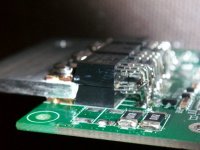
Once I tried stacking FETs on top of each other.

Double Stacked 4110s.jpg

This is still in use today. Since the current sharing is not even, I figure the rating will be about 1.5x the single FET, not double.
A piece of 1/8" aluminum bar fits perfectly between the stacked FETs. All the legs are just in parallel. This was a BMS application, so switching speed was not an issue. Usually there are separate gate resistors for each FET in a parallel setup, but I have seen them just paralleled with single gate resistor in some designs too. Apparently the issue is high frequency ringing on the gate line that you want to dampen. With the stacked FETs, there isn't much inductance between the parts, so not so prone to ringing.
 
AmpAnthony said:
I just have NCEP01T13A around for no cost. I will use only one type of mosfet so Rds should be the same and share load equally. For higher current, I will use cables, fet-s will not be in original location. If controller/motor will be unrepairable afterwards, it is no problem, I`m quite new to electric bikes world and that kind of experiment is fun :)
Sounds like you have a plan. Please keep us informed how you progress.

Answers to your questions:
2) Gate resistors: I would double the gate resistor value to each mosfet (if you double the mosfets). Reasoning being, that the mosfet drivers provide a limited amount of current. If you don't know what the specs are for the driver, then you should probably assume that the factory installation is using them at/near full capacity. So, if you double the load (double the mosfets), then you should ensure that they only draw half of the peak current each -> double the gate resistance to each mosfet. Otherwise, you run the risk of blowing the driver.
4) Short cicuit: As Fetcher said, depending on the capacitance of the old vs new mosfets, there is a chance that they will operate slower, and crossover can occur. In your case, only one way to find out: trial and error !
 
Back
Top