• Hello ES! We could use some help to get us past the finish line on building the new knowledgebase for the forum.
    Can you donate? Please see our fundraising page. Thank you!

Alternative to copper sandwich

TRS300

⚡ Regular
Joined
May 31, 2025
Messages
117
Location
Los Angles
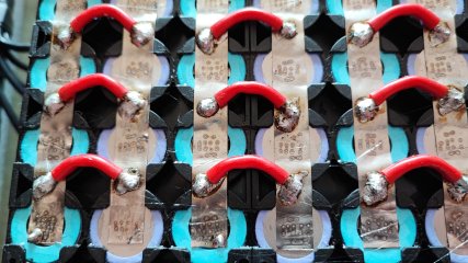
Hi All, I've finally gotten around to gearing up to make my first battery and I'd like to get some feedback to this design idea. As a reference I'm using 21700 P50B cells to build a 13s4p battery. I'm designing each parallel series to handle 20A continuous although I doubt that will be the normal demand.

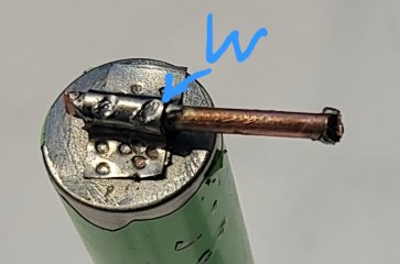
I'm thinking of making my connections as shown in the pictures. Part A gets soldered to the 12 gage copper wire (off the battery). The wings of part A get spot welded to the battery. Part B overlays Part A and gets spot welded to A. It also is welded at the points shown as W.

I did the mockup on an old 18650 cell I had and yes the wrapping on that cell is damaged so no need to focus on that.

The copper wire sits about 1mm off the face of the battery so no rubbing issues. I also plan to coat the copper wire to protect from corrosion. I actually could possibly leave the original wire sleeve on it also.

I used the nickel coated steel strip that was included with my welder but I plan to get pure Nickel strip for the build. I'll need to decide on the size strip so any suggestions will be appreciated. Thank you.
 

Attachments

  • 20250808_105520.jpg
    20250808_105520.jpg
    228.5 KB · Views: 29
  • 20250808_105440.jpg
    20250808_105440.jpg
    192.6 KB · Views: 29
Last edited:
This is not a bad concept, in principle. You understand that any current passes through the nickel first, then into the copper 12 gauge? It's a very short distance, but it's still there. I know the copper wire is technically resting on top of the cell, but you can't count on that for current carrying capacity, as there's no direct connection, just incidental connection.

May I ask why you're wrapping part B over A? I think it might be overkill.

My final note is that while I it does work in principle, consider whether you want to do this to 13s4p, all 52 cells.
 
Thanks for your input. Much appreciated. You are correct that the power still needs to pass from the battery Through parts A&B to reach the copper wire. But as you noted it's a very short distance. Part a is soldered to the wire so that path is probably better than the weld points. Part B is added to assist in the current going through the Nickel connection. Two 0.15 strips is 0.3 total. Same concept as doubling the strips between cells.
As for the effort it's actually quite easy to make Parts A and B. If you just churn them out it shouldn't take very long. But before I do that I want to get input on the concept and possibility what size Nickel strip to choose.
 
Last edited:
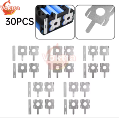
I think people sell battery contacts like this off the shelf if that helps...

Thanks for the suggestion! I've googled looking. No matter what I find I'll need to modify it for the connection I'm thinking about. If I were mass producing of course making custom clips would not make sense. But honestly, after cutting the strip to the right length all you do is wrap it around the wire and use plyers to form the clip by squeezing the strip to take the round shape of the wire. My guess is it might take an hour to make a batch of the clips and solder them to the wire jumpers.
 
Kind of weird to bother making that odd clip shape. Tin conducts slightly worse than nickel and silver considerably better. I'd say 60% silver solder is probably just as good a conductor as nickel anyway.

So no benefit in making a weird nickel clip shape to surround the copper when you can just solder the copper down to flat nickel. And nickel is very hard so people don't really crimp it.

People who want more conductivity from the soldered connection generally run the wire longer along the plates and solder a longer joint. And to hold things mechanically in place is usually handled differently by things like kapton tape and heat shrink.
 
The idea seems plausible. But why not just weld copper sheet to the cells, seems like it would be a real time saver. Unless these connections are the power wires feeding the controller I’m not sure I see the benefit.. Also carful of solder running onto the nickel that will be getting welded to the cell.. iv had some strange outcomes trying to spot weld when solder was over the nickel strip..
 
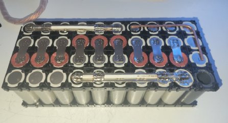
I ended up with laying down two layers of nickel strips and then adding a hammed flat 10 gauge copper jumper between the outer most batteries. It actually wasn't very difficult to do. The copper jumper make it so not all current needs to pass though the center point of the nickel strips. I'll likely not do another layout like this. Learned alot being my first battery build.
 

Attachments

  • tmp-1758210958593_1080x1920.jpg
    tmp-1758210958593_1080x1920.jpg
    164.8 KB · Views: 32
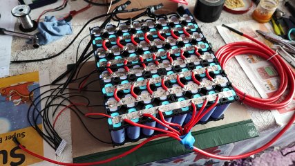
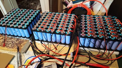
I did something similar with 0.15/10mm nickel strip and awg 14 silicone wires to a 24s 8p pack (3x8s in series, I charge them in parallel with an 8s charger).

I don't have strong spot welds and recently I've realised that from the cell to the selicone wire the nickel strip alone carries the load. But it workes so far.
I even mounted a thermo probe glued on the nickel and it showed similar temp as the probe on the cells to my surprise. And I've electronically checked that the probe makes contact with the nickel strip.
It's true that the batt has a huge voltage drop at more than 12kwh (nut sure the reason, maybe the nickel strip) but I usualy use like 4-6kwh and the voltage drop is like 6-8v.
 

Attachments

  • IMG_20230227_123502.jpg
    IMG_20230227_123502.jpg
    3.4 MB · Views: 24
  • IMG_20230321_160100.jpg
    IMG_20230321_160100.jpg
    3.4 MB · Views: 23
  • IMG_20230318_095120.jpg
    IMG_20230318_095120.jpg
    3 MB · Views: 21
  • IMG_20230919_160241.jpg
    IMG_20230919_160241.jpg
    2.2 MB · Views: 24
It's true that the batt has a huge voltage drop at more than 12kwh (nut sure the reason, maybe the nickel strip) but I usualy use like 4-6kwh and the voltage drop is like 6-8v.
So you are seeing that voltage drop at around 70 amp current draw? Unless I'm not seeing this correctly the nickel strips are your balance connections, which should not be seeing much current. Are you certain that the wires you used truly are pure copper?
 
Yes, the nickel strips join the cells in a parallel group and not see much current. My concerne is about that 3-4mm nickel strip left and right of the series wires towards the cells. You see, the series connections that carry the load are not on top of the cells but between them. Although the load from the series connection splits in two, towards left and right cells thus having 12-14 sectors of nickel between the series wires to which the entire load is splitted.
The 0.15x10mm pure nickel being rated at 7A it means it's ok untill 7x12=84A 7.2kw.
At 70A, and about 6kwh the 6-8v voltage drop is normal I think.
The wires are the well known and used in rc hobby for their 200C temp sillicone cover and I think they all are copper, I mean I haven't seen any other material mentioned but copper any time I've searched for them over the years.
It's not an issue for me because I don't need more than 7kw power.
 
Back
Top