
Ianhill
1 MW
- Joined
- Sep 25, 2015
- Messages
- 2,896
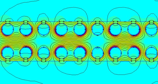
At the edge of the tooth the winding is facing away from the rotor so it's best to have 0 end turns but it's just not possible in reality and soon as they become floating from the core they become sleepy and Freddie will get them and that's the story for most motors pushed way to hard the dreaded end turn failure.
Really we want to look at the machine/motor final rpm and pole count work out its frequency and base a winding gauge on this so skin effect is kept in line and use a litz winding wire kept tight to the core to dissipate it's heat straight into the laminates encapsulate the end turns with a thermal potting to help keep them cool and the stator rear direct to case from there with water or air cooled
If it's a single stage rotor and stator use a hallbach array to focus the field at the single stator but I like the dual idea for little width gain twice the power is available but it is more complex of a design to much for me I can't even work the motor design software lol just love all the different designs and appreciating how they work.
The rotor I've seen on these aerospace grade motor are carbon so they can change rpm extremely fast for robotics type application I'd pinch as many ideas from latest tech to get a simple design that is cost effective and lethal.
It's all down to the shape of the motor for rpm really if it's pancake it will have slow rpm but a crazy fool could make a multistage design in a small can with the magnets in the centre around the size of a 80 can rc motor with double figure kw power and being dual stator the width can be fatten up on the rotors magnets the diameter reduced and with the field acting from both sides it would rip along good rpm ramge steong torque and direct to case cooling both sides be a proper ripper but hard to make specially diy, China bang them out in a heart beat could clean up if they started dropping them on us.


")

