bigdaveakers
10 mW
- Joined
- Jan 29, 2019
- Messages
- 31
I have done a quick teardown and some research as I have renewed hope that I can get this thing working!
The unit is a rear motor controller from a Mitsubishi Outlander PHEV that has a ~60kW capability as I understand
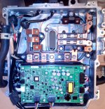
Here it is with the lid off, nicely engineered and modular. There are 2 external connectors, on that is basically a 6 pin resolver connection to the motor, and the other a CAN connection to the EV CAN network in the car along with power.
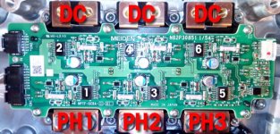
This is the control board that looks like a prime candidate for replacement with a VESC.
CN0 and CN1 are the external connections.
CN6 is some sort of comms to the driver board - I suspect this is carrying temperature and fault data for each IGBT.
CN7 is connected to the Capacitor and a power resistor. I believe that this is used to drain the capacitor after shutdown or upon request (there is a dedicated hardwired input on one of the external pins).
CN2 is connected to the current sensors, for some reason there are only 2 phases that are sensed.
CN4 and CN5 are both 6 wire connectors - one will be the PWM outputs for the drivers, the other??
View attachment 7
The capacitor is rated at 450V 700uF
View attachment 6
Underneath the capacitor, not a lot to see other than it is purpose made for the job!
View attachment 5
I believe that the sole purpose of the resistor is to discharge the capacitor at shutdown.
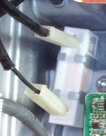
The current sensors are sat in here monitoring 2 phases. 4 wire connection to the controller board
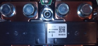
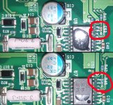
The driver board is laid out in 6 neat sections with what I believe to be a sensor section on the right. You can clearly see t1, t2, and t3 connections on the board which I suspect to be temperature sensors.
View attachment 2
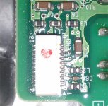
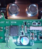
This is a closeup of the optocoupler, it was covered in 'stuff' which I assume was used to conceal the part number. However, gentle persuasion removed the stuff and they are seen to be 34JT devices.
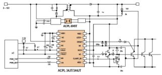
And here is the pinout taken from the spec sheet.
As mentioned these controllers can be picked up really cheaply as they dont fail so no one needs them. They are well designed, have had millions spent on R&D and have components that are specifically chosen to do the job. The IGBTs are water cooled and everything is laid out logically. It could be a really cheap way to create a motor/controller combo for conversion projects.
https://www.ebay.co.uk/itm/Mitsubis...5:g:VocAAOSwLUpaXoDZ:rk:1:pf:1&frcectupt=true
https://www.ebay.co.uk/itm/Mitsubis...6:g:jooAAOSwMBdb2t1Y:rk:1:pf:1&frcectupt=true
The unit is a rear motor controller from a Mitsubishi Outlander PHEV that has a ~60kW capability as I understand
Here it is with the lid off, nicely engineered and modular. There are 2 external connectors, on that is basically a 6 pin resolver connection to the motor, and the other a CAN connection to the EV CAN network in the car along with power.

This is the control board that looks like a prime candidate for replacement with a VESC.
CN0 and CN1 are the external connections.
CN6 is some sort of comms to the driver board - I suspect this is carrying temperature and fault data for each IGBT.
CN7 is connected to the Capacitor and a power resistor. I believe that this is used to drain the capacitor after shutdown or upon request (there is a dedicated hardwired input on one of the external pins).
CN2 is connected to the current sensors, for some reason there are only 2 phases that are sensed.
CN4 and CN5 are both 6 wire connectors - one will be the PWM outputs for the drivers, the other??
View attachment 7
The capacitor is rated at 450V 700uF
View attachment 6
Underneath the capacitor, not a lot to see other than it is purpose made for the job!
View attachment 5
I believe that the sole purpose of the resistor is to discharge the capacitor at shutdown.

The current sensors are sat in here monitoring 2 phases. 4 wire connection to the controller board

The driver board is laid out in 6 neat sections with what I believe to be a sensor section on the right. You can clearly see t1, t2, and t3 connections on the board which I suspect to be temperature sensors.
View attachment 2
This is a closeup of the optocoupler, it was covered in 'stuff' which I assume was used to conceal the part number. However, gentle persuasion removed the stuff and they are seen to be 34JT devices.

And here is the pinout taken from the spec sheet.
As mentioned these controllers can be picked up really cheaply as they dont fail so no one needs them. They are well designed, have had millions spent on R&D and have components that are specifically chosen to do the job. The IGBTs are water cooled and everything is laid out logically. It could be a really cheap way to create a motor/controller combo for conversion projects.
https://www.ebay.co.uk/itm/Mitsubis...5:g:VocAAOSwLUpaXoDZ:rk:1:pf:1&frcectupt=true
https://www.ebay.co.uk/itm/Mitsubis...6:g:jooAAOSwMBdb2t1Y:rk:1:pf:1&frcectupt=true


