Doctorbass
100 GW
BIONX MOTOR TECHNICAL REVIEW:
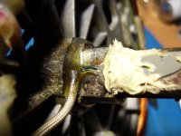
Last weekend, When discussing about my 7 familly ebikes project to the boss of the "LE PEDALIER" bicycle store, he gaved me a broken BionX hub motor explaining me that the owner said it had water inside and did a strange sound and then stopped working. so it's a warranty return
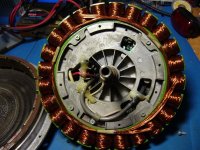
As you know this hub motor have the controller inside the stator structure.
Here is some info i am getting from this motor:
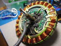
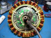
- The number of winding tooth is 24 and the stator have a total diameter of 176.6mm
- it have 3 hall sensor with 120 degree spacing
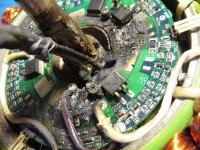
- The controller board is located in the middle of the stator and the mosfet sink their heat with the stator aluminum central structure.
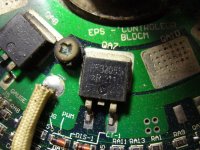
-The mosfet are the known IRF3205 also used in the crystalyte DC brushed controller.
it's the PL250 (250W) and it use 6 mosfet ( two per phase) but the board have placement for 6 other additional mosfet..
probably for the 350W model.
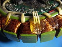
- Each phase of the winding have 7 run of wire with similar size of the nine continent and that have a AWG gauge size of AWG22 equivalent ( 0.62mm dia.) of max recommanded current of 7 amp and that have a max frequency ( skin) of 42kHz and i estimate the number of turn per tooth to around 10 turn ( ex: a 5304 have 4 turn)
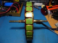
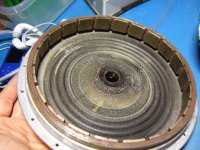
-The rotor is made of 22 magnet of 20mm width and 3.1mm thick
-The central lpart of the stator is made of aluminum and the stator winding ring structure is fixed with screw to the aluminum central structure.
The controller board is definitively completly scrapp and a larg part of the PCB has burned... eee TOASTED dur to a mosfet explosion!
So the controller is no more usefull.
If the guys of the store accept to give it to me
I plan to remove and BYPASS the controller... and will push it with a 18 mosfet controller to the max temp limit ( around (135 degree C usually is the ok limit)
SO HOW MUCH POWER DO YOU THINK I'LL BE ABLE TO USE WITH IT BEFORE IT heat too much ?? 8) :wink:
Doc
Last weekend, When discussing about my 7 familly ebikes project to the boss of the "LE PEDALIER" bicycle store, he gaved me a broken BionX hub motor explaining me that the owner said it had water inside and did a strange sound and then stopped working. so it's a warranty return
As you know this hub motor have the controller inside the stator structure.
Here is some info i am getting from this motor:
- The number of winding tooth is 24 and the stator have a total diameter of 176.6mm
- it have 3 hall sensor with 120 degree spacing
- The controller board is located in the middle of the stator and the mosfet sink their heat with the stator aluminum central structure.
-The mosfet are the known IRF3205 also used in the crystalyte DC brushed controller.
it's the PL250 (250W) and it use 6 mosfet ( two per phase) but the board have placement for 6 other additional mosfet..
probably for the 350W model.
- Each phase of the winding have 7 run of wire with similar size of the nine continent and that have a AWG gauge size of AWG22 equivalent ( 0.62mm dia.) of max recommanded current of 7 amp and that have a max frequency ( skin) of 42kHz and i estimate the number of turn per tooth to around 10 turn ( ex: a 5304 have 4 turn)
-The rotor is made of 22 magnet of 20mm width and 3.1mm thick
-The central lpart of the stator is made of aluminum and the stator winding ring structure is fixed with screw to the aluminum central structure.
The controller board is definitively completly scrapp and a larg part of the PCB has burned... eee TOASTED dur to a mosfet explosion!
So the controller is no more usefull.
If the guys of the store accept to give it to me
I plan to remove and BYPASS the controller... and will push it with a 18 mosfet controller to the max temp limit ( around (135 degree C usually is the ok limit)
SO HOW MUCH POWER DO YOU THINK I'LL BE ABLE TO USE WITH IT BEFORE IT heat too much ??
Doc
Attachments
-
 P1070896_800x600.jpg109.4 KB · Views: 6,756
 -
 P1070898_800x600.jpg126.9 KB · Views: 6,779
 -
 P1070899_800x600.jpg105.7 KB · Views: 6,779
 -
 P1070900_800x600.jpg128 KB · Views: 6,753
 -
 P1070901_800x600.jpg66.7 KB · Views: 6,746
 -
 P1070902_800x600.jpg101 KB · Views: 6,748
 -
 P1070903_800x600.jpg109.7 KB · Views: 6,743
 -
 P1070904_800x600.jpg116.4 KB · Views: 6,766