Bonanza "Bulldozer" Dual PhaseRunner AWD

Alan B said:
GCinDC said:
How wide? You gotta be careful down at the bottom near the pedals...

Clearance between my pedals is 5.5". These batteries are 2" high, so about 4.5" total width. So about 1/2" inside of the pedals clearance. Is that enough? I'll verify things before building.

I'm planning to use a 1/4" thick triangular plate of plastic right down the middle, and clamp everything to that. Then cover with waterproof nylon pulled snug with some airflow openings, probably attached permanently at the top and velcro for opening it. Perhaps a fan on the controller but with a 6x10 9C and 12 4110 FETs it should run pretty cool. I'm trying to make it serviceable with reasonably good access to the components.

I think that 1/2" on each side is more than enough, just make sure that you have a nice firm attachment, but still have some allowance for vibration/give. I like to have some rubber between the frame and the box if possible, and I didn't see what kind of plastic you are using, but I'd avoid things like plexi-glass (acrylic) and use something that can take abuse like ABS and flex rather than fracture.
 
Alan B said:
Clearance between my pedals is 5.5"
You mean between inside of cranks? That include smallest gear on front chainring too? If the triangle goes down to bottom bracket, you may notice some gears down there... not sure what they for tho... :lol:
 
I have been thinking that perhaps cellcore ABS or FR-4 pc board material might be good. It has to be tough! Have not located the plastic yet.

I also like the idea of some mount flexibility, perhaps rubber grommets in the mounting. Planning to use the bottle holders in both the lower tubes. Might need to do more there.

The 5S batteries are shorter so would give a bit more clearance, but the 6S would give 4P (instead of 3P) and 12 more cells overall for more stored energy.
 
GCinDC said:
Alan B said:
Clearance between my pedals is 5.5"
You mean between inside of cranks? That include smallest gear on front chainring too? If the triangle goes down to bottom bracket, you may notice some gears down there... not sure what they for tho... :lol:

Heck, those small chainrings don't even reach the triangle on this bike!

It had been awhile since I took those measurements. You are right, there is a 2" stay-clear in the bottom of the triangle to clear the chainrings. The aluminum tubes are so large on this mountain bike that the triangle does not overlap the chainrings much. The cranks are straight from there on out. So I'll have to stay out of the bottom 2" of the triangle or so on the chainring side, at least with taller stuff. Looks like that can be done by shifting the batteries up slightly.

Thanks for noticing,
 
triangle18clean.jpg
 
Somehow, that does not strike me as a very practical layout. I would ditch one unit and arrange them to where they are parallel to the downtube. In addition, you could double-up and place 6 x 2 where the batteries are sharing the open space. The overall width will still be narrow enough for your thighs to move freely :)

My 1/2W, KF
 
Thanks for your comments and suggestions KF.

Not sure I quite understand your suggestions. The current plan is to mount a plastic plate centrally through the triangle, and put components on both sides, clamped to the central plate (perhaps use T-nuts and long screws to hold top plates for each battery or group of batteries, plus thin foam rubber to provide a firm grip on each battery). One side has the 12 FET controller and 5 batteries, the other has 7. The goal is 12 batteries total. This makes the system about 5 inches wide which is all the width available. Batteries are about 2x2x6.

The batteries can be 5S or 6S Lipos. 12 of them give 20S3P or 18S4P with the 5S or 6S packs, respectively. I'll probably go with 18S4P for 1.4kwh. This produces a max speed of about 27 mph with the 6x10 9C motor and a range of about 40 miles at 35 wh/mi.

If I remember correctly, 3 batteries won't quite fit along the downtube. Any more even stack that I tried so far produced much fewer batteries and a lot more unused space.

Thanks,
 
Alan B said:
The current plan is to mount a plastic plate centrally through the triangle, and put components on both sides, clamped to the central plate (
Covering with cordura will waterproof this, but in the event of a wipeout? Did you see what I did with steel frame? Easy to make into triangle with tin snips, very cheap, and thin enough so won't use up much valuable real estate...
file.php
 
Thanks for the photos Greg! Very compact. Amazing how much you have packed into that tiny space.

I'm hoping to make something a bit more accessible and serviceable since I'm doing so much experimenting and development. It probably won't be as crash worthy. I may use thick G-10/FR-4 PCB type material for the center triangle, that stuff is very tough. The outside plate clamps on the batteries would take any impact from the side (and squeeze the batteries). Of course the pedals, cranks, seat and handlebars make it difficult for impacts to reach the triangle, but in a collision all bets are off.

I'm not committed to a design yet, just exploring possible ideas. May need to mock something temporary up with some MDF and see how it plays.
 
Alan B said:
hoping to make something a bit more accessible and serviceable...
a sciene fair with wheels! :lol: but your diag doesn't really account for the wires... they take up space coming out of the corner. they can be smashed a bit, but when it comes time to wire, you may find yourself needing more room for all those packs. and will you parallel the ones on opposite sides? on which side will they mate? you may find the serviceability suffers with all the additional wiring and crazy routing required... you may find yourself wishing for a brick instead... :lol:

i made my pack so i could open it up, but with db25 giving me access to all 20 cells, i didn't need to for a year...
 
I save those white boxes the Lipo come in - while obviously oversize compared to the Lipo brick they come in handy for me to mock-up layouts. The oversize is helpful allowing room for wiring and any buzzer/LVC cutoff devices required to fit inside the installation.
 
The wiring is going to be interesting. I'm planning to play with wiring before finalizing on the layout. It will definitely change things as it gets worked out. I was thinking about using the spaces between the packs for some terminal blocks and make everything pluggable. It will get more interesting.

Perhaps I'll start with a cheap piece of quarter inch plywood and make a prototype to see how it goes. I think keeping the parallel blocks on the same side is probably better, but one set will need to cross the panel. Drilling holes is not hard but things have to line up so as not to drill into a pack on the far side, or at least to avoid having the wire come out under a pack.

I can always duct tape them into a block if this doesn't work out!

Anyone else done a panel mount in the triangle before?
 
bms6mpc005.jpg


Updated my per-cell microprocessor based BMS design for Lipo connectors (but still a work in progress..). Might have to build some of these. Just doesn't seem to be much out there. Above is the Battery Management board, there is another Master board that has the rest of the logic to interface to the controller, etc. Up to 8 Battery Management boards can connect to one Master. Each Battery Management board can handle up to 6 cells (and up to 6 parallel packs). So a 20S pack requires four Battery boards, while an 18S pack requires 3 Battery boards. The Master board has throttle and ebrake interfaces as well as serial and USB interface for computer readout of cell voltages and programming of parameters. Also LCD for local readout.

Received some more Lipo. The Crystalyte battery box will hold two 5S and two 6S 5AH packs, so 11S 10AH. Interesting. Not a bad package. There is still room in the box for some BMS. Probably won't use that on this bike, but for another project that will start soon.

Ordered more 4mm bullets, out of stock again at HK. Have a few, will need more.

New 6x10 9C hubmotor wheel is re-rimmed and re-spoked and in shipment. New freewheel, shifter to match. Should have late next week.

Need to find another tire for the new wheel. Or remove it from the old wheel. Is the Schwalbe Marathon Plus 1.75 the best choice, or should I consider another tire?

Ordered a Topeak MTX DXP rack and bag. Looks good for carrying things when commuting and making it easier to do some testing with batteries in the bag.
 
Dude, weren't you just a Noob a couple months ago? hehe. What's that board for? In layman's terms...

And when did you scrap plans for a headway pack. What was the decisive factor?

If you can't wait for the bullets, PM me. I got extras... :mrgreen:
 
Hi Greg! Was listening to you on the podcasts a few days ago. Fun stuff. Link:

http://endless-sphere.com/forums/viewtopic.php?f=18&t=19548

The challenge with the Headways is mounting them. When I solve that in a satisfactory way I'll probably use them, too. I now have 16AH Headways and 5S as well as 6S 5AH Turnigy 25C Lipo. The Headways are a bit heavier and bulkier than the Lipos. But they will probably last longer.

So I've a few choices. I'm not really happy with mounting any of these batteries yet, still looking at various ways to go.

On the BMS, I want plug and play charging management and low cell voltage protection, with full cell level info. Modular, in small bites to fit into the spaces left between other things. I don't have room for another big box or board. These Lipo do have nice cell level plugs on them, so take advantage of that. The Battery board above is the low level part. It will parallel the taps of the already paralleled batteries (like GGoodrum's boards), so 3 or 4 of them would be required for an 18S or 20S pack. The main chip there is a microprocessor with 10 bit voltage reading capability so it can measure cell voltage to 5 millivolts resolution. It has an output controlling a balancing resistor, and an optically isolated serial connection to the separate "Master" board.

So, in layman's terms, it can read each cell's voltage, and it can control a bleeder resistor for balancing. It can be programmed to do various things with this information depending on what is required.

These micro chips have flash memory to hold their programming, and all the usual processor and registers. Each pin is multipurpose and can be programmed to do different things at different times. This particular chip is about a buck. It can be had in various packages from 8 pin dual in line down to small and smaller surface mount. This one can run 8 million instructions per second on the internal clock. I can write software in "C" and download it into the chip with a $20 programmer that connects to the six pins shown.

So we can do low voltage monitoring by having the master poll each channel at a few of times per second, and we can do charge control and balancing similarly. The master would have an output to turn the charger on/off so it can stop the charging before any cell goes too high, and then after balancing the cells it can top them up as the lowest cell catches up. We can put filtering and hysteresis into the software to prevent oscillations and react better to intermittent connectors. Updates are generally software changes/reloads rather than making new boards. I would make the software in the battery board CPUs very simple, all the stuff that would be more likely to change would be in the Master (so reloading the more numerous battery monitor micros would not happen much). It is also possible to load software into the master via USB once the boot loader is installed there.

I'd also put a USB interface on the master for setting and reading all the cell parameters. Also an LCD for displaying the battery detail info. Low cell, high cell, etc. But mostly it can be ignored knowing that if any cell gets too low it will let you know by some means like momentarily dropping the throttle, etc. When you want to know more it will be there. Without having to hook up celllogs, etc.

I already have a commercial board that can do the master part. It has LCD, buttons, buzzer and lots of I/O and program space.
 
I unpacked the hitch mount bike rack that arrived a few days ago. My old hitch mount bike rack sticks through the triangle and won't work if I fill the triangle with battery. This one grabs the wheels and top bar. There may still be some issues with the top bar clamp but I can work that out. It has pretty good ratings and looks well made. I have not tried it on the truck yet. It is a Swagman XC-2 no 64650 from Amazon.

I also have a Yakima StrongArm (if I remember the name correctly). I don't think it is made anymore. It is a tire track type with a heavy curved arm that grabs the crank. It might work on an ebike though the weight of the bike will put more than the usual force on the crank and arm. It is mounted on top of the 4Runner so it is a bit high to lift the ebike.

I want to have a good rack for those times I need to carry the bike, or get an emergency pickup.

I'm also looking at ways to carry the ebike when we tow the trailer. Some folks have mounted Yakima racks on the rear deck of the Avalanche (our tow vehicle), or they can be mounted on the roof. Again that is pretty high. The deck would be an easier lift but is more in the way when accessing the bed storage. Here is the link to the rear deck mount for the Avalanche:

http://www.chevyavalanchefanclub.com/cafcna/index.php/topic,94316.0.html

Any suggestions on a good internet source for Schwalbe Marathon Plus 1.75 tires? Not sure the LBS is going to have that.
 
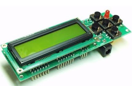
Here is the "Master Controller" I plan to use, and a bit of daydreaming about what to do with it. This commercially made board is by Olimex and is available from a lot of other places as well. It is amazing what you can get for 60 bucks!! A link to Sparkfun:

http://www.sparkfun.com/products/37

atmega128a.jpg


atmega128b.jpg


Some features (and what they can be used for):

* ATMega128-16AI processor with 128K Bytes Program Flash, 4K Bytes data EEPROM, 4K Bytes RAM
* - Note this is a HUGE programming space for an embedded micro and will hold an amazing amount of code!
* - It can be programmed with GCC, the free C compiler used for Linux, and most free software
* ICSP 5x2 pin STKxxx compatible connector for in-circuit serial programming (for initial programming)
* RS232 connector with TTL levels (to talk to battery manager boards)
* RS232 DB9 female connector (computer interface for programming, etc)
* Dallas touch button port (could be used for a sophisticated key)
* Frequency input (possibly monitor PWM duty cycle?)
* LCD 16x2 display with LED Backlight
* LED status indicator (could be a warning indicator (motor/controller warm, battery almost low, etc)
* Five buttons (select display, parameter, up/down value, enter)
* Buzzer (another warning indicator, motor/controller hot, battery nearing shutdown)
* Power supply circuit +5V, 78L05 with DC power jack and diode bridge requires 12VDC Input
* RELAY with 10A/250VAC NO and NC contacts with screw terminals (control the charger)
* Many I/O pins available for things like measuring temperature, etc (motor, controller and ambient temperature)
* PWM pins that can be filtered and produce analog output for throttle control (cruise control, power/speed limiting, low batt warning)
* Output pin for controlling ebrake input to controller for motor/controller overheat or battery cell low voltage shutdown
* Collect serial output from Cycle Analyst and record data as well as display select items
* Could take input from a GPS and record/display that. (could plot motor temperature on Google Earth...)
* Dimensions: 120x36 mm (4.7x1.4")

It will require a housing to protect it from weather.
 
Looks like the same or similar one to what JackBauer uses for his DIY pack charger:
http://www.diyelectriccar.com/forums/showthread.php/200-build-your-own-intelligent-charger-36627.html
 
amberwolf said:
Looks like the same or similar one to what JackBauer uses for his DIY pack charger:
http://www.diyelectriccar.com/forums/showthread.php/200-build-your-own-intelligent-charger-36627.html

Interesting thread over there. Can't see the photos as I don't have an account there. May have to fix that. The processor board he links is exactly the same one I'm using.

They mention expensive programmers and software, but those are not required. There are programmers starting at about 15 bucks and free software as long as you can program in "C". The same compiler and programmer can be used to make code for the little 8 pin processors on the battery management boards.

On the charger part, I've also been thinking along similar lines (they used a DIY switcher right off the line) so I can have a super lightweight and small onboard charger. But that is something for later on.

Thanks!
 
Alan B said:
Here is the "Master Controller" I plan to use, and a bit of daydreaming about what to do with it. This commercially made board is by Olimex and is available from a lot of other places as well. It is amazing what you can get for 60 bucks!! A link to Sparkfun:

http://www.sparkfun.com/products/37

atmega128a.jpg


atmega128b.jpg


Some features (and what they can be used for):

* ATMega128-16AI processor with 128K Bytes Program Flash, 4K Bytes data EEPROM, 4K Bytes RAM
* - Note this is a HUGE programming space for an embedded micro and will hold an amazing amount of code!
* - It can be programmed with GCC, the free C compiler used for Linux, and most free software
* ICSP 5x2 pin STKxxx compatible connector for in-circuit serial programming (for initial programming)
* RS232 connector with TTL levels (to talk to battery manager boards)
* RS232 DB9 female connector (computer interface for programming, etc)
* Dallas touch button port (could be used for a sophisticated key)
* Frequency input (possibly monitor PWM duty cycle?)
* LCD 16x2 display with LED Backlight
* LED status indicator (could be a warning indicator (motor/controller warm, battery almost low, etc)
* Five buttons (select display, parameter, up/down value, enter)
* Buzzer (another warning indicator, motor/controller hot, battery nearing shutdown)
* Power supply circuit +5V, 78L05 with DC power jack and diode bridge requires 12VDC Input
* RELAY with 10A/250VAC NO and NC contacts with screw terminals (control the charger)
* Many I/O pins available for things like measuring temperature, etc (motor, controller and ambient temperature)
* PWM pins that can be filtered and produce analog output for throttle control (cruise control, power/speed limiting, low batt warning)
* Output pin for controlling ebrake input to controller for motor/controller overheat or battery cell low voltage shutdown
* Collect serial output from Cycle Analyst and record data as well as display select items
* Could take input from a GPS and record/display that. (could plot motor temperature on Google Earth...)
* Dimensions: 120x36 mm (4.7x1.4")

It will require a housing to protect it from weather.

:shock: Awesome. I have been playing around trying to reprogram a Turnigy Watt Meter to act as the brains for my friction drive, just because it had a screen, uC, shunt etc, in one little cheap package. But the 2k program memory limit was really limitting my options. This, with a few extra odds and ends, might just be able to do everything I need without too much hassle about optimising code. Thanks a lot for the link.

- Adrian
 
Spent part of an evening with a new to me program called FreePCB and nearly finished a small pc board to parallel the balance taps from 6S Lipo packs. It provides a DB-9 connector for the charger and four JST-XH connectors for Turnigy packs. Not bad to learn a new program and get some work done that quickly.

parallel%20board.jpg


I'm planning to send to to BatchPCB and get some prototypes made. If it works out it can be added to their "catalog" and other folks can order boards directly from them. Pretty neat system! Has anyone used that PCB setup? They panelize all the various projects and send them to Gold Phoenix for production. Cost is about $2.50 per square inch for double sided plated through boards with solder mask and silkscreen on both sides. Handling is $10 per order so it pays to either make a few of one board or batch a few different boards at the same time. Sparkfun does this and uses the same service for their board production, so I guess I have some of these boards already in that form. The one downside is 3-4 weeks turnaround.
 
The Hubmotor returned with new rim and spokes, 6 speed shimano megarange freewheel and the SRAM twist shift to match. Looking good! Thanks to Holmes Hobbies!!

Submitted the pc board to batchpcb but their rule checker found some errors. Have to figure out what it doesn't like. Ordered some more Turnigy silicon wire for the battery wiring. Charged the 5S and 6S packs, all look reasonable. Have to make up some wiring to test with.

Was looking at the new Zero electric motorcycle and their removable battery pack. Would be nice to be able to do that on the bike. Hard to do that with 18S4P 20AH pack... Will give that some more thought.
 
Back
Top