ivannnivano2000
🔌 New-ish
I want to run a Bosch Gen 4 torque sensor on a VESC controller, so I measured its harness. The coil arrangement turns out to be a closed ring of four equal coils, i.e. a bridge. I have not found this documented anywhere, so here are the numbers. What I still need is the excitation the Bosch drive unit applies to it.
The sensor
Measurements (unpowered, disconnected)
Resistance:
Diode mode:
What that says
Wires 1-4 are a closed ring of four equal coils. For a ring of four equal elements R, adjacent nodes must read R||3R = 0.75R and opposite nodes 2R||2R = R. Taking R = 30.1 ohm from the diagonals predicts 22.58 ohm for every adjacent pair, against 22.6 / 22.7 / 22.7 / 22.7 measured - 0.3 % across four independent pairs. That matches the four coil designators on the board.
A four-element ring tapped at all four corners is a bridge: excite one diagonal (1-3), read the imbalance on the other (2-4). Torque unbalances it. Note this also means a single adjacent pair cannot be driven in isolation - current takes the 3R path around the ring as well.
Wires 5-8 are a separate network, coupled to the coils only through megohms. 5-6 reads the same in both directions in ohms mode (the ohmmeter's sub-0.3 V never opens a junction) but shows a clean 0.734 V silicon drop in diode mode - so a resistor in parallel with a junction, i.e. it goes to the IC: probably ESD structures, possibly an NTC for temperature compensation. 7-8 is capacitive, no junction.
The coils themselves come out to the connector directly, with no silicon in the path - a junction in series would have destroyed the 0.3 % symmetry above.
Questions
I will post whatever I measure - inductance, excitation, the front-end schematic - back into this thread, so it ends up documented somewhere public.
@stancecoke - you have done a lot of work on open source ebike firmware and on torque sensors, so if you have ever looked at what a Bosch drive unit puts on this connector, or have a view on driving this bridge, I would be very glad to hear it.
--- UPDATE: after opening the drive unit ---
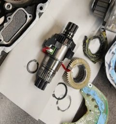
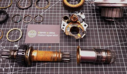
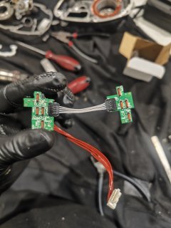
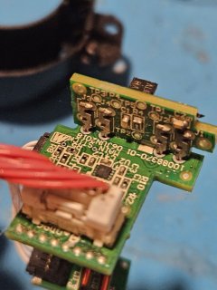
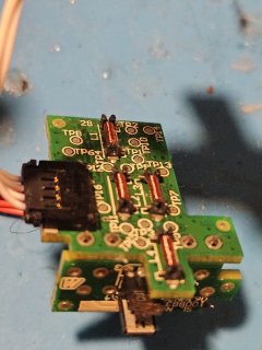
The sensor has eight coils, four on each of the two boards. So each 30.1 ohm bridge arm is two coils in series, roughly 15 ohm each - electrically a ring of eight coils tapped at every second junction, with the 4-5 way flex between the boards carrying those nodes across. I suspect the windings alternate at plus/minus 45 degrees, since torsion puts the principal strains there and that would make bending and temperature common-mode, but I have not confirmed it yet.
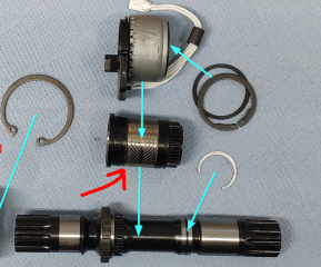
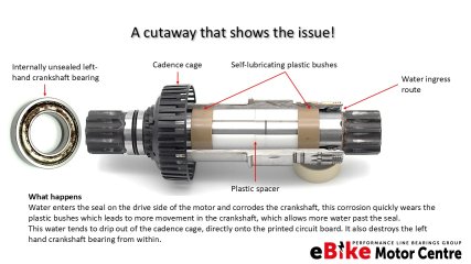
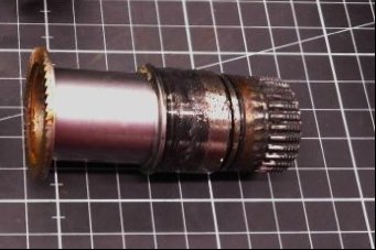
The spindle carries a magnetic band or sleeve, so the sensor is useless without its own bottom bracket. What I still do not know is whether that band is permanently magnetised or only magnetostrictive. That decides the whole front end: a magnetised band emits a torque-proportional static field, which a plain coil cannot see and which needs a fluxgate-style drive, whereas a magnetostrictive band changes permeability, i.e. inductance - which is exactly what a bridge is built to measure. The bridge topology argues for the second.
On the drive unit PCB, right next to the 8-pin sensor connector:
So the architecture looks like: MCU clock -> flip-flop -> quadrature reference -> excite one diagonal through 33.2 ohm, pick up the other differentially, synchronous I/Q demodulation, result back to the MCU.
Which sharpens question 1. The excitation frequency is not set by any RC network or crystal on the analog side - it is the MCU clock feeding that flip-flop, divided down. So: has anyone scoped a powered Gen 4 board at the torque sensor connector, or at that flip-flop's clock pin? Any frequency figure, even approximate, would save me a lot of work.
And question 2 becomes a ten-second test for anyone with a spindle on the bench: hold a small compass against the band on the shaft. If the needle reverses, the band is permanently magnetised. If it only attracts, it is not.
The sensor
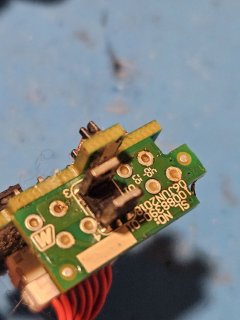
- Two small boards joined by a short 4-5 way flex, test points TP1...TP16, coil designators L1, L3, L4, L7 next to wire-wound coils, one QFN IC (U2) carrying a two-letter marking only.
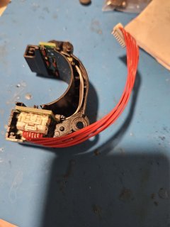
- Assembled it is a horseshoe carrier that encircles the BB spindle without touching it - so contactless inductive coupling.
- Harness: 8 wires, 8-pin fine-pitch JST (~1.0-1.25 mm). All eight wires are the same red colour, so everything below is numbered by connector position, pin 1 taken from the connector key.
Measurements (unpowered, disconnected)
Resistance:
Code:
  1-2   22.7 ohm        1-3   30.1 ohm
  3-4   22.7 ohm        2-4   30.1 ohm
  1-4   22.6 ohm        1-7   open
  2-3   22.7 ohm        3-7   open

  5-6   6.45-6.47 kohm, identical with the probes reversed
  7-8   18.2 -> 26.6 -> 27.96 kohm, drifting upward on every reading
  1-5   ~5 Mohm, wandering
  3-5   ~4 Mohm, wandering
Diode mode:
Code:
  5-6   1.130 V forward    0.734 V reverse
  7-8   2.917 V forward    2.905 V reverse   (both about open)
What that says
Wires 1-4 are a closed ring of four equal coils. For a ring of four equal elements R, adjacent nodes must read R||3R = 0.75R and opposite nodes 2R||2R = R. Taking R = 30.1 ohm from the diagonals predicts 22.58 ohm for every adjacent pair, against 22.6 / 22.7 / 22.7 / 22.7 measured - 0.3 % across four independent pairs. That matches the four coil designators on the board.
A four-element ring tapped at all four corners is a bridge: excite one diagonal (1-3), read the imbalance on the other (2-4). Torque unbalances it. Note this also means a single adjacent pair cannot be driven in isolation - current takes the 3R path around the ring as well.
Wires 5-8 are a separate network, coupled to the coils only through megohms. 5-6 reads the same in both directions in ohms mode (the ohmmeter's sub-0.3 V never opens a junction) but shows a clean 0.734 V silicon drop in diode mode - so a resistor in parallel with a junction, i.e. it goes to the IC: probably ESD structures, possibly an NTC for temperature compensation. 7-8 is capacitive, no junction.
The coils themselves come out to the connector directly, with no silicon in the path - a junction in series would have destroyed the 0.3 % symmetry above.
Questions
- What excitation does the Bosch drive unit apply to this connector - frequency, amplitude, sine or square? This is the one number I cannot derive. Anyone who has scoped a BDU at the torque sensor connector, even roughly, would save me a lot of work.
- Is the spindle part of the magnetic circuit? Magnetised band, mating ring or winding opposite the horseshoe? In other words, is the sensor useless without its own bottom bracket?
- Does anyone have the pinout of this 8-pin connector, or know which pins carry supply and which are the coil ring in Bosch's own numbering?
- Has anyone conditioned a sensor like this with an AD630 (balanced modulator/demodulator) or AD698 (LVDT conditioner)? My plan is an oscillator into diagonal 1-3, differential pickup off 2-4, synchronous detection referenced to the oscillator, low-pass, then into an ADC input. Any experience with excitation frequency, drive level, or how much the zero drifts with temperature is welcome.
I will post whatever I measure - inductance, excitation, the front-end schematic - back into this thread, so it ends up documented somewhere public.
@stancecoke - you have done a lot of work on open source ebike firmware and on torque sensors, so if you have ever looked at what a Bosch drive unit puts on this connector, or have a view on driving this bridge, I would be very glad to hear it.
--- UPDATE: after opening the drive unit ---
The sensor has eight coils, four on each of the two boards. So each 30.1 ohm bridge arm is two coils in series, roughly 15 ohm each - electrically a ring of eight coils tapped at every second junction, with the 4-5 way flex between the boards carrying those nodes across. I suspect the windings alternate at plus/minus 45 degrees, since torsion puts the principal strains there and that would make bending and temperature common-mode, but I have not confirmed it yet.
The spindle carries a magnetic band or sleeve, so the sensor is useless without its own bottom bracket. What I still do not know is whether that band is permanently magnetised or only magnetostrictive. That decides the whole front end: a magnetised band emits a torque-proportional static field, which a plain coil cannot see and which needs a fluxgate-style drive, whereas a magnetostrictive band changes permeability, i.e. inductance - which is exactly what a bridge is built to measure. The bridge topology argues for the second.
On the drive unit PCB, right next to the 8-pin sensor connector:
- two precision resistors marked 33R2 = 33.2 ohm in the drive lines. Against a 30.1 ohm diagonal that is a source-impedance match, and it says the bridge is driven differentially across one diagonal - which matches what I measured from the sensor side.
- a TSSOP-8 marked V74 / 03D8, which looks like a 74LVC2G74 dual D flip-flop. Fed a 4x clock, that is the standard way to generate the 0/90 degree quadrature reference pair for a synchronous detector.
- a quad high-side driver VNQ7050A sits nearby, but I rang it out and it has no connection to the sensor connector - it drives something else, probably the light output.
So the architecture looks like: MCU clock -> flip-flop -> quadrature reference -> excite one diagonal through 33.2 ohm, pick up the other differentially, synchronous I/Q demodulation, result back to the MCU.
Which sharpens question 1. The excitation frequency is not set by any RC network or crystal on the analog side - it is the MCU clock feeding that flip-flop, divided down. So: has anyone scoped a powered Gen 4 board at the torque sensor connector, or at that flip-flop's clock pin? Any frequency figure, even approximate, would save me a lot of work.
And question 2 becomes a ten-second test for anyone with a spindle on the bench: hold a small compass against the band on the shaft. If the needle reverses, the band is permanently magnetised. If it only attracts, it is not.
Attachments
Last edited: