Brushless controller tuning modifications

I took it for a spin with all packs
I put a wireless camera on my helmet and recorded it.you can see the pseed on the gps. it's recorder 15fps so the values on the gps
are sometime a bit weird looking.
I reached 61km/h tops.

here's the video

 
your controller may be shutting down because the voltage to the voltage regulator may be too high. you need to go see what the input and output of the 12V regulator is when it has all the packs in place.

or you could use the converter like richard outlined in his thread. find one that uses 120 V AC, and then open it up and attach the top of your 88V pack to the output of the rectifier bridge on the input of the charging brick (AC adapter). you can then use the output from the charging brick to feed the input to your voltage regulator if it is above 12-13V, up to 18V is ok too. if you can only get 12V out of the AC adapter then just bypass the votage regulator and put your connections right on the 12V rail where the capacitor is and use that for your controller current, and put it on a switch to keep from discharging your pack when it is not in use. you actually could get away with taking a 14-15V output and using it directly, but it is best to go through the regulator.

you will have to deal with the LVC though, if you use a DC converter source for your controller current. but you can make a resistor bridge off the 5V rail to the LVC resistor to keep the LVC signal line high enuff that it doesn't shut down. the setpoint is about 2.58mV on the infineon 846 chip.

also you can modify your current DC converter by finding the Vin to the oscillator pwm IC controller in that 8 pin package. look up the spec sheet and find Vin on the oscillator IC. then follow the trace on that pin back towards the input to the transformer and you will find a resistor in that line which you can change (decrease the resistor to increase the current through it to Vin) and that may allow the oscillator to start up if it sees a higher voltage on the internal voltage divider inside the Vin pin input.
 
dnmun said:
or you could use the converter like richard outlined in his thread. find one that uses 120 V AC, and then open it up and attach the top of your 88V pack to the output of the rectifier bridge on the input of the charging brick (AC adapter). you can then use the output from the charging brick to feed the input to your voltage regulator if it is above 12-13V, up to 18V is ok too. if you can only get 12V out of the AC adapter then just bypass the votage regulator and put your connections right on the 12V rail where the capacitor is and use that for your controller current, and put it on a switch to keep from discharging your pack when it is not in use. you actually could get away with taking a 14-15V output and using it directly, but it is best to go through the regulator.
Do you mean something like this ?

powerschematic.jpg

and in the 72v controller it will be connected straight to the LM317 which makes a clean 12V and 5V ?
 
My next project will be a cell monitor for my lipo's on my instrumentspanel.
You maybe know the cell-log 8S from hobbycity. They are perfect to do the job and give it a nice look.

CL8S.jpg


once opened you only have a pcb with the lcd attached.

2009-10-26132441.jpg


Then i will put those 3 and mount them together on another pcb board and connect it to a 25DB connector which goes
to the battery compartment under the seat.

display1.jpg


I then have to cut the instruments panel of my scooter to fit those tiny screens. and cover it up with some
seethrough watertight plastic.

displayonscooter.jpg


I allready ordered 2 more of these cell-logs. So keep you updated with this project
 
yes, your power lines to the FETs is separate from the controller current line. the controller current normally goes through those big power resistors to drop some voltage before it enters the voltage regulator. if the power resistor is too low in value then the voltage on your voltage regulator could be too high and that pulls the 12V and 5V rails up inside, which might cause the controller to shut down. usually they just blow up and smoke a lot.

if you use the idea from richard of opening up a regular AC adapter for charging a laptop or other mid voltage range device, then you can use the output from your high voltage battery and attach that voltage right inside the AC adapter where the rectifier diodes normally have output. since you don't have AC then you need to get right to the rectified side of the diodes to make your connection from the battery.

that voltage will then drive the oscillator circuit in the switch mode power supply and the AC adapter then will become a DC-DC converter producing DC volts identical to its rating from normal AC operation. usually 19V for a laptop.

then you would use this 19V output and connect that directly to the input side of the LM317T and that would then create the normal 12V and 5V circuit currents.

the problem with using a separate source than the main Vcc for the input is that the LVC resistor divider bridge is also taking it's high lead voltage off of the Vcc and if you have no voltage there, then the microprocessor will shut down because it needs a voltage on that LVC detect pin to operate.

you can defeat this, and use your DC converter, if you can make a new bridge that runs from the 5V rail over to the top of R12. on the infineon this resistor to ground is 1200ohm and the high side of the bridge is 17megohm for a cutoff at 30.5V of about 2.6mV to the pin on the microprocessor. so if you use 5V, use a resistor smaller than (5/30.5)x17Megohm or smaller than 2.78megohm.

your processor may be different and have a different processor and inputs, but the idea would be the same for any processor that needed to have fixed replacement voltage for the LVC.

track it down and we can help, richard knows this stuff better than me though.
 
dnmun said:
yes, your power lines to the FETs is separate from the controller current line. the controller current normally goes through those big power resistors to drop some voltage before it enters the voltage regulator. if the power resistor is too low in value then the voltage on your voltage regulator could be too high and that pulls the 12V and 5V rails up inside, which might cause the controller to shut down. usually they just blow up and smoke a lot.

I'm trying to find out which resistors i have to replace around the LM317 on my board.

Test 2: the old 48 controller is a infineon one! i opened it up and saw the exact type of the thread: Infineon Controller Technical (by knuckles)
so i will order more powerfull FET's and some new caps. and resistors which i also be needing for this controller.

Question: which FET's should i get. they talked about the IRFB4310 or the 4110s you'd adviced.

And is it possible to read out the flash prom which parameters it's now programmed with ? or should i just flash it with the parameters you all advice in the forum? i'm currious what these parameters now are set on with this 48V config. before i change them with new ones.
 
you may wanna see if you can run with the p75fn75 FETs you have now. the bigger concern is the caps, which have to be upgraded since they are all 63V parts i think. but maybe the 48V controller had the 100V caps.
 
Neat project! Looks like "dean's connectors" in that bag you got there.

You're running a 24ah pack? How many amps are you pulling? What kind of lipo are you using? If its like the saggy economy lipo I have, that could be the reason your scoot is cutting out maybe.
 
dnmun said:
you may wanna see if you can run with the p75fn75 FETs you have now. the bigger concern is the caps, which have to be upgraded since they are all 63V parts i think. but maybe the 48V controller had the 100V caps.

I think we are confusing the controllers. The one you see in this thread is the new one . the caps are all 1000uf/100V

It's the one i removed out of the scooter which was a 48V type i'm gonna modify with 4110s from methods and new caps 100V types.
 
vanilla ice said:
Neat project! Looks like "dean's connectors" in that bag you got there.

You're running a 24ah pack? How many amps are you pulling? What kind of lipo are you using? If its like the saggy economy lipo I have, that could be the reason your scoot is cutting out maybe.

Thanks Bro!

I use Dean's connectors on every lipo pack. and about the amps...haven't checked that because my Watt's Up meter only run's on 60V max.
(at least i think....) dunno anyone tried higher voltages ...

I'm gonna place a 50A shunt to measure what it's pulling out of those lipo's

The first shutdown was because of the DC/DC convertor !! that one died when it got 87Volts!
Then my 120A/12V circuit breaker went off...i first thought it was my controller...but in fact it was the DC/DC convertor which was blown up.
Now i did a bypass with a seperate lipo of 14.8 to provide the power for my lights etc.

After doing that i had no more problem connecting all lipo's fully charged on the controller! no shutdowns !

The shutdown in my first testrun was because i had installed a lipo pak with only 72 volts ( fully charged!)
so when it gets a load from the hub motor it went down to 64V and that's why the controller shutted off.

I will give a new update with some grphs how the lipo's are holding and how much ampere i use.
 
Looks like its the ebay ecp/akku lipo? 2p mine does drop lots of volts under load, wasn't sure it would do it at your 6p tho. It'd be great if you could post what kind of amps you're pulling vs. how many volts you drop. This lipo is really great ah per $ but nobody has posted test results on its performance. I had assumed it was maybe 4c capable even though it is advertised as 15c. Now I'm starting to think more like a real 2c.. anyway when my HC watt meter comes in I will be able to compare notes.
 
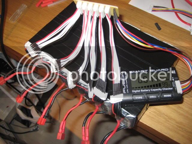
I used at first ECpower lipo's from Ebay, then i switched to another lipo brand "WinForce" but they are all look-a-likes.

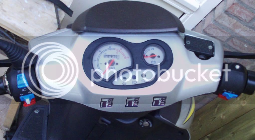
i did a test run today to see what one of my 6S6P packs did in performance at high speed.

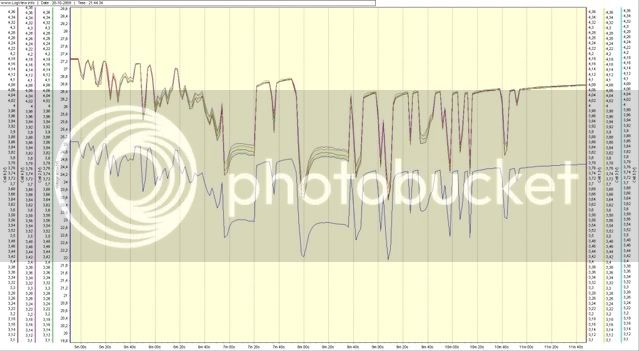
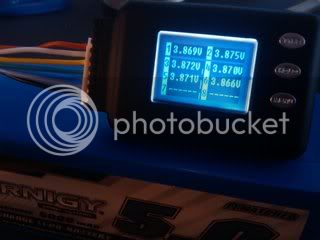
This the graph showing the voltages from all 6 cells and the total voltage.
6S6P60kmh.jpg


a short report with all min-max values are:

Voltage accu
Maximum value: 25,089 at position 2
Minimum value: 21,943 at position 274
Range: 3,146
Average: 24,435

Cell 1
Maximum value: 4,181 at position 0
Minimum value: 3,648 at position 274
Range: 0,533
Average: 4,07

Cell 2
Maximum value: 4,183 at position 0
Minimum value: 3,671 at position 274
Range: 0,512
Average: 4,078

Cell 3
Maximum value: 4,183 at position 0
Minimum value: 3,668 at position 274
Range: 0,515
Average: 4,075

Cell 4
Maximum value: 4,184 at position 0
Minimum value: 3,682 at position 274
Range: 0,502
Average: 4,08

Cell 5
Maximum value: 4,177 at position 2
Minimum value: 3,638 at position 274
Range: 0,539
Average: 4,064

Cell 6
Maximum value: 4,181 at position 0
Minimum value: 3,636 at position 274
Range: 0,545
Average: 4,067
 
Nice graph! That is the output from the 8s turnigy monitor? How many amps were you pulling at "position 274."
 
vanilla ice said:
Nice graph! That is the output from the 8s turnigy monitor? How many amps were you pulling at "position 274."

This runs on a brushless hub motor. and i measured just one of the 4 packs (6S + 6S + 5S + 4S)
i still have to connect my shunt and measure the amps...i think i will do that in the weekend.
because when i'm back from work..it's to dark to do some measurments etc.
 
Any updates? I'm really curious about the amps vs. voltage drop on these affordable lipo packs.. 2.25Wh per dollar shipped lipo is a hard to resist deal.
 
vanilla ice said:
Any updates? I'm really curious about the amps vs. voltage drop on these affordable lipo packs.. 2.25Wh per dollar shipped lipo is a hard to resist deal.

Coming UP !

Just received last week a cycle analyst. had to figure out how to mount that sweet thing and how to connect the speed magnetic switch at my frontwheel of my scooter.

i'm gonna make a special video-splashscreenmix. Watch Out! :shock:
 
MrKang said:

Hey I have a question not about your build, but about that smart guard checker you're using.
We were discussing them in another thread and I did some googling but there's not much info about on them.

How have you found the capacity indicator ? Does it just work off voltage ? Is it just the balance connector that it reads from or can the main discharge leads run through the device too (to measure current) ?
Does it have a balancing feature as well ? ( I saw one ebay add for one advertising that it balances but it isn't mentioned elsewhere in other listings)

Thanks
 
Hi Hyena,

This SmartGuard is just a tester. it reads of the cell voltages and makes his capacity readout from the voltages of the cells.
it doesn't ballance the cells. It was recomended by RC freaks because it was very accurate.
My friend uses this one from hobbyking.

cell-medic-1.jpg

This one has the abbility to balance and discharge the pack. but with small discharge rates...not very useable for 20ah or more packs.just for RC heli and stuff.
 
Hyena and Mr. Kang,

I agree that as shipped those hobby king units don't have sufficient discharge capability to balance our larger packs... but comeon guys, when has that ever stopped us?

Hyena - order what you need... chop off a 1/2" bar of aluminum stock... mount some BEEFY resistors there and clamp it to your frame for better dissipation and jumper from the HK units to your ballast loads = )_

Messed up part is I'm sure there are much cleaner ways of improving these but I picked up samples to re-engineer last time, this time it's yours (though I'm tempted to buy just one).

-Mike
 
mwkeefer said:
Messed up part is I'm sure there are much cleaner ways of improving these but I picked up samples to re-engineer last time, this time it's yours (though I'm tempted to buy just one).

-Mike

Hi mwkeefer,

Are you gonna modify a HK tester/balancer/discharger with higher resistors so they can discharge better ? What do you mean by re-engineer and what ?
I'm currious now?
 
Thanks for the info Mr Kang.
I'm aware of the other hobbycity ones. It was more those smart guard ones with the large % remaining display that I was interested in. I'm building a few bikes for friends who need a simple fuel gauge type display and though this would be a good option. If only it measured current as well and displayed used ah instead of just voltage drop it'd be ideal.

Mike, cutting and shutting certainly isn't beyond me! Those devices would be a good option too because you could remove the back of it, mod the resistors and add a heat sink and then mount the top half of the case in a hole in your battery box. I really barely need a balancer though. Aside from the one weak pack I posted about in the turnigy thread (the one that got wet) all the other packs have a max delta v of 0.01v after a full charge, and this is after 100+ cycles with no balancing.
 
This sundaynight i had the time to replace the new Fet's from method into the old 48V controller.
I was happy when i grabbed my old dusty Hakko 484 desolder buddy which was all dusted away in a far away corner.
Turned it on ..and ...brrr...brrr...sucked like a little pigplet. So first unscrewed all fet's which were mounted on the coolingplate.
Than piece by piece desoldered all Fet's and all the wires which are used to connect the hub-motor.
Screwed the new Fet's first on the coolingplate , not to tight, and then put it all back into the holes of the pcb.
Soldered them tightly and fresh with some new solder..hmmm...love the smell of it !..hehehe

After that i replaced the 3 caps with 2 new ones. 1000uf/100V. Put a JST Female connector on the data line for programming this sucker later.
Only have to place the two resistors back for 5W types (330E & 680E) so it is functional with 100V.

I hope my wires & plugs are coming this week from hobbyking. i see that they left at 5 and 7 nov. so...maybe i'm gonna finish it next weekend.

Here some pics:
2009-11-09223024.jpg

2009-11-09220419.jpg
2009-11-09220433.jpg

2009-11-09220458.jpg
2009-11-09222944.jpg

2009-11-09231554.jpg
2009-11-09231615.jpg
 
My goal is to go to work on my E-Scooter instead of driving 1.5 hours in traffic jams. Here in the netherlands we have many heavy traffic jams arround 8am.
The distance i have to drive is arround 50km (google route). I want to capture the route wth a small camera on the front of the scooter. together with a gps tracker and the info from my cycle analyst and the log from the cellogs (4 pieces, each logger on a lipopack) i want to make a complete video screen with all data.

I have been experimenting first with exporting a gpx file into google earth which i can playback..and then i bumped on the first problem.
If it playes back the gpx it isn't shown realtime. So i was trying to change some options and parameters but that ended up with no succes.

After googling my problem i ended up with a 3rd party software app. which imports a gpx file and then uses google earth as a player !

Super !!! see here: http://www.hybridgeotools.com/

So..after figuring that out it was time to test it out. On a normal working day i used the car and recorded the route with gps and camera mounted on my rearview mirror. Then at work i imported the gpx file and used a little program called "Frapps" to capture my screen. I played the gpx file and saw in realtime the exact route on google earth. With the movie that was created in Frapps i also used the amera movie and then combined them with a video program editor. I normaly use adobe after effects. The total output was super !

Next step is to record all 4 lipo packs with the cellogs and use the data to move some meters and implementing that into the video.

The dashboard of my scooter will be modified into a brand new customized dash with 4 cellogs and the CA display and the lights from the turning signals.

All my stuff from hobbyking are at customs!! so i still have nothing received..still waiting for 16Lipo's 50 meters of wire and extensions and a variety of plugs and connectors. Hope they will come this week....
 
finally my 1st package arrive out of custom inspection.. it stayed there about 12 days after leaving china with EMS.
Next time i won't spend the extra bucks for EMS shipping because it finally ends up in hold off at custom inspections here in the netherlands.
first i received a letter where to put in a invoice of the parts i ordered with the value of it. Then after 7 days they finally released it. I had to pay 27 euro's !! and 17 of it was for custom decleration administrations...That's a brand new 5000mA Lipo dudes !! i was thinking..

When i opened the box i was wondering if all lipo's are ok.

2009-11-18134543.jpg


After testing them all they were all healthy !! ahhh...that puts a load of my mind..

Now i have to wait for the other 3 Batches which also are at customs on 5th november....still waiting !!!! :x
 
speaking of the devil!
BATCH 2 is in da house! and together with a custom decleration i have to fill in for batch nr.3...damnit...

2009-11-20122431.jpg


TWO2GO!
 
Back
Top