You are using an out of date browser. It may not display this or other websites correctly.
You should upgrade or use an alternative browser.
You should upgrade or use an alternative browser.
Building a triple stator axial flux motor
- Thread starter Lebowski
- Start date
Lebowski
10 MW
Harold in CR
100 kW
Moving along nicely 8) 8)
liveforphysics
100 TW
Very cool!
Lebowski
10 MW
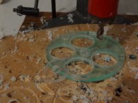
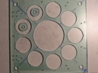
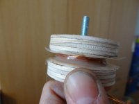
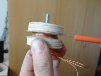
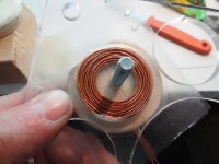
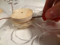
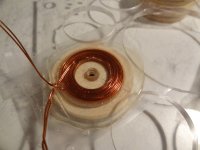
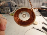
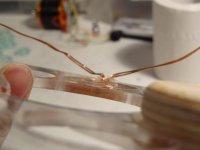
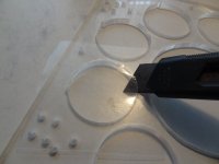
Now for what I find the most difficult part of building the motor, the glueing of the coils.
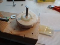
Basically what we want to do is wind a coil soaked in glue, transfer it to the coil plate, clamp
it in place and leave it to cure for 24 hours. After that we need to remove the clamp without
destroying the coil.
I've tried different types of glue and ended up with epoxy. Next to being strong, the glue
needs to cure by means of a chemical reaction, NOT by means of the evaporation of a
solvent. Because the whole structure will be clamped tight the evaporation of solvents is
not possible. I've tried specialty acrylic glass glue but the solvent did not evaporate, leaving
me with a goo-ie mess even after 48 hours of 'drying'. Epoxy gives a beautiful and very strong
result, so I've stuck to epoxy.
View attachment 6
View attachment 5
I let the glue cure at room temperature, so the strength is around 1200N per cm squared.
The glued area is a circle of 4cm diameter, 0.5 cm high so an area of roughly 6 cm^2.
7200N is roughly 720 kg, strong enough I would say . I've thought about heating
the glue to cure it faster and stronger. I'm a bit worried though about the acrylic glass expanding
slightly under higher temperature, leading to cracking when it cools down again. But passing
a current through the epoxy soaked coil would make heating easy...
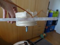
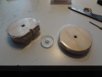
Ok, now, to make sure the wooden disks used to clamp the coil in place doesn't stick to the
epoxy I conver them in what in Holland is called 'boeklon'. Its a self-sticking thin plastic sheet
material used to cover and protect books. It is sold at book and office supply stores. Lots of
library books are covered in this stuff.
View attachment 4
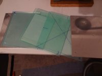
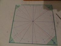
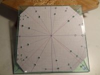
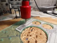
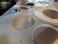
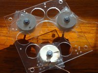
First prepare the coil plate.
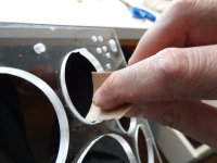
Basically what we want to do is wind a coil soaked in glue, transfer it to the coil plate, clamp
it in place and leave it to cure for 24 hours. After that we need to remove the clamp without
destroying the coil.
I've tried different types of glue and ended up with epoxy. Next to being strong, the glue
needs to cure by means of a chemical reaction, NOT by means of the evaporation of a
solvent. Because the whole structure will be clamped tight the evaporation of solvents is
not possible. I've tried specialty acrylic glass glue but the solvent did not evaporate, leaving
me with a goo-ie mess even after 48 hours of 'drying'. Epoxy gives a beautiful and very strong
result, so I've stuck to epoxy.
View attachment 6
View attachment 5
I let the glue cure at room temperature, so the strength is around 1200N per cm squared.
The glued area is a circle of 4cm diameter, 0.5 cm high so an area of roughly 6 cm^2.
7200N is roughly 720 kg, strong enough I would say
the glue to cure it faster and stronger. I'm a bit worried though about the acrylic glass expanding
slightly under higher temperature, leading to cracking when it cools down again. But passing
a current through the epoxy soaked coil would make heating easy...
Ok, now, to make sure the wooden disks used to clamp the coil in place doesn't stick to the
epoxy I conver them in what in Holland is called 'boeklon'. Its a self-sticking thin plastic sheet
material used to cover and protect books. It is sold at book and office supply stores. Lots of
library books are covered in this stuff.
View attachment 4
First prepare the coil plate.


Lebowski
10 MW
Lebowski
10 MW
parabellum
1 MW
Beautiful^2 
Harold in CR
100 kW
Very clever. Nicely done. Never thought wire that thick could be used.
salty9
1 kW
This thread is getting as addictive as the CNC thread is. 
numberonebikeslover
1 kW
wow this is so nicely done. Amazing job. Two thumbs up for you buddy. I also intend to do something like this with my axial flux alternator in future. I am sure I would learn a great deal from this thread and would love to follow it all the way
Good luck to you lebowski.
with kind regards.
Naeem
Good luck to you lebowski.
with kind regards.
Naeem
Sancho's Horse
1 kW
This is really nice.
salty9
1 kW
With the proper potting materials this would be a good design for a cast stator.
Limber passages in the stators and proper vanes in the rotors should generate a decent cooling breeze.
Limber passages in the stators and proper vanes in the rotors should generate a decent cooling breeze.
Lebowski
10 MW
salty9 said:With the proper potting materials this would be a good design for a cast stator.
Limber passages in the stators and proper vanes in the rotors should generate a decent cooling breeze.
Adding vanes to the rotor will be one of the last steps. This will then blow air through the cap between the coil plates
and the magnet plates. V1 has no vanes but this effect is already present there. To protect the (open) motor against
the rain I sometimes put a plastic bag upside down over the motor. The airflow blows the bag up like a balloon...
Lebowski
10 MW
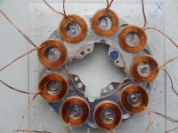
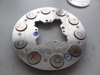
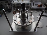
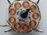
The motor we're building is a triple stator motor. I've decided to wind with 2 wires in parallel so that I can put the 3 stator plates in series and
still have a voltage that should give me 1000 to 1500 rpm in 20s Lipo (80V). Another option would have been to wind with only 1 wire, so have
a higher voltage per plate. Then we would have needed to terminate in delta, of which I'm not a fan (see one of my other posts). Even worse
than delta would be to connect the 3 plates in parallel. In this case you run the risk of one plate delivering a higher voltage than the other (even though
rpm is the same), one plate is then supplying current to the others, which comes with a power and efficiency loss. The voltage of a plate depends on the magnetic
field strength it sees, which in turn depends on the distance between the rotor plates. This last factor will be impossible to make absolutely equal for all
three stator plates. So, parallelling stator plates is not an option. Finally there's the choice of running each stator plate with its own controller,
while technically interesting and certainly possible with my controller IC, it will require a lot of hardware in the form of at least 18 FETs with 9 driver
IC's etc etc, expensive.
So, 3 plates in series it is. Before we wire up 3 plates I first want to wire up 1 plate and see whether the voltages etc are the same for all 3 stator
plate locations.
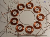
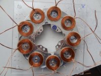
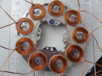
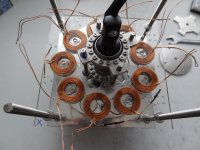
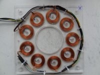
The motor will have 10 magnet poles and 9 coils per plate. The winding calculator shows it should be connected in AaABbBCcC... or is it AaAbBbCcC ?
Or some other variant ? To keep it clean I want all wires to enter the plate together and leave the plate together.


Brentis
10 kW
Such an impressive and inspirational build.
Many thanks for sharing your creativity so openly and effectively. Lots of pics, I like.
Hope you dont mind, but I have spent the past week in Sketch up drawing various versions of the many great ideas you have shared. Literally 40hours. Pics to come.
I think I am going to attempt a single stator version first just to prove to myself that I can do it.
I have a couple of newbie bldc theory questions to ask if you get some time.(Or any other motor brains here)
1. Describe to me the relationship between magnet strength/size vs. amount of copper per coil?
- For a fixed motor width, should I pack in the biggest/strongest magnet possible or maximize copper? whats the ratio?
-I understand that air gap is critical for producing maximum potential.
2. You are using 10poles 9winding, 25mm magnet with 40mm windings wound 2x25 0.8mm to achieve a given kV.
If I used 10poles 9winding, 30mm magnets 30mm windings wound 2x25 0.8mm, Would kV go up or down ?
3. All other parameters equal, would 1 x 25 1.6mm wound remain @ present kV?
4. So many questions, lets get my head around those first.
Again thanks for sharing. You have my vote for Build the Year so far.
Subscribed.
Lebowski
10 MW
Back in the day before I started the build of v1 I did some equation to see whether the thing was viable and could drive a bicycle. I will post the equations here in a few weeks (am about to go on holiday for a week now, flying to Tenerife in a few hours  ). They answer your questions and give some good guidelines as far as design choices go.
etard
100 kW
I was just wondering what ever happened to Axial Flux! Nice work!
Lebowski said:Njay said:At least some (not sure if it's your case) axial flux motors are closed only by the magnet's force. So, if we could slightly adjust the separation of rotor and stator "on the fly" by some screws or whatever, that would give us a kind of transmission box (continuous or discreet), having a torque-oriented final reduction and increasing separation to achieve higher speeds.
Ehm, this is torque control by decreasing efficiency, not the way I would want to go :?
Mechanical flux weakening was used by solar racing teams a long time ago
The trick is to optimize the gap for a given load/rpm
You can eek out more efficency
Not worth the trouble IMO
http://www.autonomie.net/docs/6 - Papers/CIL/axial_flux_variable_gap_motor.pdf
Efficency decreases as the air gap increases
**£except in the low torque region
Awesome motor by the way! Can wait for a video of it running!
Brentis
10 kW
Lebowski said:Back in the day before I started the build of v1 I did some equation to see whether the thing was viable and could drive a bicycle. I will post the equations here in a few weeks (am about to go on holiday for a week now, flying to Tenerife in a few hours). They answer your questions and give some good guidelines as far as design choices go.
Cheers, very much appreciated.
To do my part I downloaded a couple of Uni. papers on bldc, pmsm, ac sync. motor construction.
(here is a good one for anyone interested http://web.mit.edu/scolton/www/SCThG.pdf)
A good portion of which is way over my head especially the math.
So your input and practical experience is very welcome.
My dream is to have a direct drive hub with the following stats ;
100 ftlbs torque. 1000w cont. 4000w peak. 10 kv approx.
less than 150mm in diameter, fits 135mm drops.
In this model i have used 30mm x 15mm http://www.supermagnete.ch/eng/S-30-15-N
Coils are 30mm diameter 20mm thick.
Choices where made as a function of available space.
Diameter of motor is only 144mm. Easily hidden by gearset/brake.
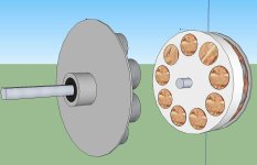
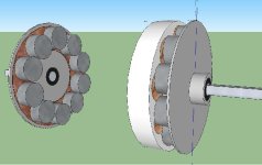
Do I have even half the power requirement in a design like this?
Lots to learn.
Enjoy the vacation
Kingfish
100 MW
The Dude’s work here is refreshing and enjoyable to follow! 8)
Without meaning to steal thunder...
Brentis, your requirements are similar to an early study I conducted on the Doing the Math thread. The first half unfortunately is difficult to read due to character corruption introduced by amateur handling of the ES database transfer from one owner to the next, however the essential formulas are readable from the Sun Oct 02, 2011 2:22 pm post on forward.
From the information you provided – diameter, rotation, power, torque – we can calculate the theoretical physicality of the motor. I used a spreadsheet to iterate on the numbers until I came up with a good understanding how I wanted the motor to be, and then moved on to model in in FEMM for more refinement.
Best of luck! KF
grindz145
1 MW
That is fn cool. Can't wait to see this thing spin up.
Brentis
10 kW
To avoid clogging up this awesome build thread with my newb questions,
I have created a dedicated thread to do my edumicating.
http://www.endless-sphere.com/forums/viewtopic.php?f=30&t=47670
I have created a dedicated thread to do my edumicating.
http://www.endless-sphere.com/forums/viewtopic.php?f=30&t=47670
Similar threads
- Replies
- 25
- Views
- 6,507
- Replies
- 484
- Views
- 71,214


