• Howdy! we're looking for donations to finish custom knowledgebase software for this forum. Please see our Funding drive thread

Building a triple stator axial flux motor

Nice modeling! :)

Earlier in the thread Lebowski showed a diagram with an "ideal yoke":
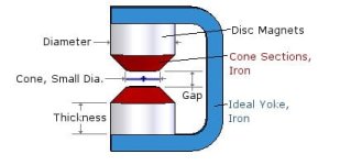
Screenshot-8.jpghttp://endless-sphere.com/forums/download/file.php?id=104807

If I understand correctly the Yoke bridges from one magnet disk to the other -and from one magnet to it's opposing brother (sister?!..).
How would this configuration compare with the ones you are now modeling?

-Structurally an advantage would be that the yoke would be plenty strong to keep opposing magnets from attracting and flexing towards one another (so the structural aluminum plates holding the magnets and iron could be thinned down). Of course this configuration would require the stator to be attached from the axle instead of from outside -making it an outrunner motor.
 
Miles said:
Lebowski said:
I wonder, what if we take your proposed situation but get rid of the 'focussing' magnet and just make the main
magnets so big that they practically touch ?
Then you'll get much more flux short-circuiting...
Agreed. The rule of thumb is to use the magnet thickness as the basic guide for magnet spacing.

I think that with the smaller square magnets that your HB effect is too small to be worth the extra cost of material and tooling for assembly; I toyed with that arrangement in my studies, and the very best that you can achieve via that route is a slight reduction in back iron thickness. However to be truly effective, the magnets have to be the same thickness for HB Array, which only increases the gain by √3 to one side, requiring little to no back iron, though 2X the tooling cost for flux in two directions on custom wedge-shaped magnets. Even with all of that - (and let's just say "money was no object" so we're not constrained financially)... the end result is still problematic on two fronts:

  • You cannot go into production using a HB Array because the patent holder would not like it.
  • It is still less efficient than traditional AF layout using a single style wedge magnet with back iron because you have 2X the distance to cover between alternating poles even though they have √3 more flux.
For myself, it was an economic decision as much as it was pure math which direction to follow. :)

From the peanut gallery, KF
 
Miles said:
Lebowski said:
I wonder, what if we take your proposed situation but get rid of the 'focussing' magnet and just make the main
magnets so big that they practically touch ?
Then you'll get much more flux short-circuiting...
yep this is what I thought too, and why I have the spacing between the magnets. It would be nice to know though what the optimum is though...
 
Lebowski said:
It would be nice to know though what the optimum is though...
You're not really losing fluxing by approaching 180deg. pole arc, just getting an increasingly poor return for the extra magnet weight/cost :) For a motor with an iron core, the spacing is critical to B-EMF waveform, harmonics, torque ripple, etc.

Maybe think about maximising the radial component of the windings, somehow? Half the copper in the round coils is contributing very little to the torque.
 
Miles said:
Lebowski said:
It would be nice to know though what the optimum is though...
You're not really losing fluxing by approaching 180deg. pole arc, just getting an increasingly poor return for the extra magnet weight/cost :) For a motor with an iron core, the spacing is critical to B-EMF waveform, harmonics, torque ripple, etc.

Maybe think about maximising the radial component of the windings, somehow? Half the copper in the round coils is contributing very little to the torque.
I know but I don't have an oval hole saw :mrgreen: but I'm still considering buying
a portal style cnc machine as I want to build more motors but want to reduce the
amount of (dirty dusty) work... With a cnc rectangular magnets and the previously
discussed focussing magnets would be no problem. Plus I can make ovals in the stator
and make oval shaped coil centers
 
How about drilling two, radially spaced, circumferential rows of small holes in the perspex plate and weaving the wire between them? :)

You can do a lot with a small milling machine and rotary table, dividing plate, etc.

I'm thinking about getting one of these for my mill: http://medw.co.uk/wiki/view/DivisionMaster
 
Sorry to interupt,
Miles: Half the copper in the round coils is contributing very little to the torque.

I was under an assumption (yes very dangerous :mrgreen: ) that a round coil was very efficient in Leb's application. (?)

if this is true in a "corless" coil, once we add a suitable core, will the generated flux be better in some other geometric form?....(still contemplating the "Mandorla" just for space considerations)

Please expound a bit on this when you have a moment.
Thanks in advance for any info. I'll shrink back into the woodwork & keep lurking here.
I love this thread.
 
Miles said:
How about drilling two, radially spaced, circumferential rows of small holes in the perspex plate and weaving the wire between them? :)

You can do a lot with a small milling machine and rotary table, dividing plate, etc.

I'm thinking about getting one of these for my mill: http://medw.co.uk/wiki/view/DivisionMaster
I cannot picture what you mean ?

I'm thinking about getting one of these for my next motor build:
http://www.sorotec.de/shop/product_info.php/language/en/info/p3530_isel-mini-flat-40-tischmaschine-mit-steuerung-und-steuersoftware.html//
 
Something like this would do a 12"x12" part. 4" max height, so your tooling would be a bit restricted. No Dust with the right vac.

mdx40_ico.png


Back on the flux focusing just a bit, is this what these bumps on each end of the stator teeth are doing ?
transmag_15.jpg
 
Thud said:
I was under an assumption (yes very dangerous :mrgreen: ) that a round coil was very efficient in Leb's application. (?)

if this is true in a "corless" coil, once we add a suitable core, will the generated flux be better in some other geometric form?....(still contemplating the "Mandorla" just for space considerations)

Please expound a bit on this when you have a moment
The winding will only contribute to torque to the degree that it runs in the radial direction. So, I don't see how a circle, or a square even, are efficient? A mandorla would be better. Some kind of weave winding, like the Launchpoint motor, would be optimum, I think.
 
I've thought about a weave (though I still don't know what you mean ? a mandorla in wikipedia is just a pointy oval ?)

For the triple stator I throught about a circular weave. I got 10 magnets per plate there, so the weave would have 10 inward/outward
wire crossings under the magnets and 5 interconnect wirings outside and inside. And then with 3 stators you can make
each 120 out of phase to get the typical 3 phase motor. I was afraid the field induced by the circular weave would generate
eddy current losses in the axle, plus it's very difficult to wind. Plus I'm not convinced (yet?) it's better as just oval winding.
An oval winding is the same as a weave but split in 2, with the feed coming from both left and right.

Just to picture what I mean with a circular weave: one for 8 magnets would look like a swiss cross with rounded corners
 
Nice looking design on the launchpoint pdf. No "buy it now" options. :( Like the way they rotate the magnets. Very compact design.

speedmd wrote:
Back on the flux focusing just a bit, is this what these bumps on each end of the stator teeth are doing?
I don't think so. I don't have another explanation, though :)

May be that the bumps are just a bit of gap tightening where the flux drops off a bit just to even things out. Has me interested. Need to get up to speed on the simulations to study it a bit further. I have seen this type of treatment on several other motors also.
 
Hmmm. I've no idea why the Laumchpoint patent file I uploaded before contained only the first page :eek:

Anyway, here's the complete document:
 

Attachments

  • WO2011139396A1 Launchpoint.pdf
    1.3 MB · Views: 452
Miles said:
Hmmm. I've no idea why the Laumchpoint patent file I uploaded before contained only the first page :eek:

Anyway, here's the complete document:

IT's kinda what I thought it would be, I don't see the fundamental advantage w.r.t. oval coils (as commented in my earlier post)
 
Lebowski said:
IT's kinda what I thought it would be, I don't see the fundamental advantage w.r.t. oval coils (as commented in my earlier post)
There's no fundamental advantage, just a matter of degree.

Lots of ideas got generated in some of the old threads on A.F. motors.
You've probably seen this before but for the benefit of those that haven't:
http://www.endless-sphere.com/forums/viewtopic.php?f=30&t=14339
 
Miles said:
Lebowski said:
IT's kinda what I thought it would be, I don't see the fundamental advantage w.r.t. oval coils (as commented in my earlier post)
There's no fundamental advantage, just a matter of degree.

Lots of ideas got generated in some of the old threads on A.F. motors.
You've probably seen this before but for the benefit of those that haven't:
http://www.endless-sphere.com/forums/viewtopic.php?f=30&t=14339
Hey I've never seen that thread :D will have a look through it, thanks !
 
I am in the midst of building an axial flux motor and have a few questions I am still not clear on even after reading this entire thread. Is iron core better or not? I cannot come to a proper conclusion on this as there seems to be some serious debate.

My next question is, how will these coils fare as coils for a motor? My intention is to make a stack of 10 of these and 11 stacks of magnets. Feedback on that idea would be much appreciated as well!

This motor should be super awesome if I execute it correctly and would happily sell as many as I can supply to the community when done!

EDIT: I forgot the link to the coils: http://www.mouser.com/ProductDetail/TDK/WR282840-37K2-LR3/?qs=hUaYk7HeIDi%2fli%2fmHLVSRg%3d%3d

Thanks in advance guys!
 
This Motor is genius !

I've read every page yet , and really want to build a coreless motor in approximately the same size, too !
I dropped the idea and motivation some weeks ago , but I've already picked it up again.
I still dont know how to design my coils and magnets layout.

Why are round magnets used ?
Wouldn't it generate more Torque to use rectangular magnets?
Also I wonder if there are formulas for calculating wire resistance/inductance
or the correct wire cross section for a specific current at a specific speed..

I dont really know where to start to get it to output 5kw continous at ~1000-2000 rpm
Power consumption allowed : 200A at 50V
 
Vendetta277 said:
This Motor is genius !

I've read every page yet , and really want to build a coreless motor in approximately the same size, too !
I dropped the idea and motivation some weeks ago , but I've already picked it up again.
I still dont know how to design my coils and magnets layout.

Why are round magnets used ?
Wouldn't it generate more Torque to use rectangular magnets?
Also I wonder if there are formulas for calculating wire resistance/inductance
or the correct wire cross section for a specific current at a specific speed..

I dont really know where to start to get it to output 5kw continous at ~1000-2000 rpm
Power consumption allowed : 200A at 50V

I used round magnets because, well, the hole saw I have makes round holes. If you get the plates laser cut I would go square...

inductance:
http://www.66pacific.com/calculators/coil_calc.aspx

resistance:
http://chemandy.com/calculators/round-wire-resistance-calculator.htm

I still have to calculate what the optimum plate and magnet spacing is, but at the moment I'm not planning another motor and have
lots of things to do for the next versions of my controller Ic...
 
Ok, here my 2c on the above magnet focusing discussion...
I had an idea a while back when working on a similar design that I put aside as it did not meet my power density requirements.
It's not really a Hallbach but the effect should be the same.
Put a magnet ring with axial magnetization the North or South pointing in or out (as needed) around your cilindrical magnets.
The gains should be similar to the hallbach test "above" but much simpler to implement.
If one could simulated the effect in 3D, I am sure it show an even better improvement.

Cheers


P.S. So it's not a Hallbach, should I patent it? :mrgreen: I'd call it the squeezee :lol:
 
squeegee,
Cannot patent that, it has already been done. You are absolutely correct and I hope someone takes your suggestion seriously. 2D FeEM shows this clearly. This also means that you can significantly reduce the thickness of the back plate on the rotor. I had actually considered (and may try this yet) 3D printing the matrix (two levels, rotor face and rotor back) that would allow the placing of these magnets, on a glass plate in the rotor shell, so they could be locked in with poured epoxy (pull a slight vacuum to get the air bubbles out of the matrix). If the 3D matrix is ABS, then acetone will melt it away after the epoxy sets. So much to try and so little time.
 
As Elon musk says. A patent is just a "lottery ticket to a lawsuit"
 
Back
Top