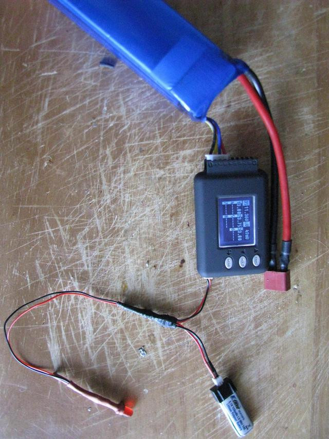
CellLog 8 hacking

This equalize drain mod interest me alot.

I wonder if it's possible to mod it to use with 6s only and have the current drain on all 7 firsts pins to be equal ?

Me and some user are using 4 x 6s packs and are using 4x(6s) x celllog8 instead of 3x(8s) becasue it's easy to make parallel 44.4V or serie 88.8V with 4 groups of 6s.

I like the jumper of D4 and D5 and the 7.5k on the first cell but is it ok only for 8s to be current balanced? or it work with 6s too? I mean does i need to have a load on the cel 7 and 8 input on the celllog?

by the way, the relay i found to mecanically insulate the celllog are very small.. maybe 5 cubic cm for 4 contact insulation.

these relay are from surplus andcost around 2$ each.

Doc
 
fechter,

Give this a shot:

Program new HVC/LVC points into the CellLog8 and then dump the HEX and EEP again... do a byte by byte compare (diff?) and see how they store variables.

I would wager the txt is stored in the eeprom memory as opposed to compiled into the HEX (binary code).

I just dug up my USB->ISP interface and will work on a dissassembly of the HEX code, being able to alter these or even develop our own open firmware for them would be useful!

Great work on the even drain mod!

-Mike
 
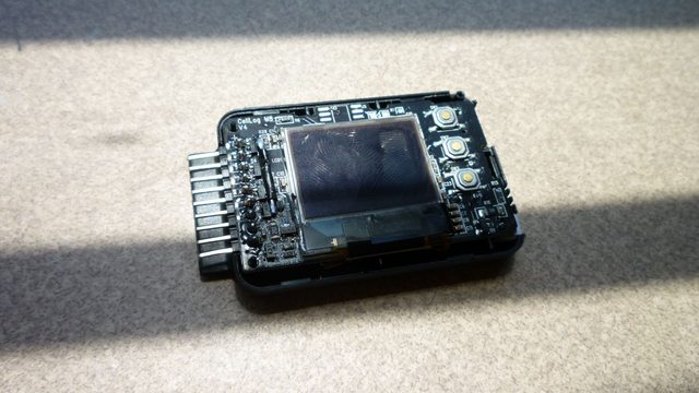
The key to developing some open source firmware for these will be to figure out the LCD interface. Once that is done, the rest should be fairly trivial.


The interface looks like it has too many signals to be chip controller based. It has too few to be a raw LCD interface.

With all those pins, it looks like the LCD may be a "video" interface type unit. These usually have the row and column drivers on board, but no intelligent controller. You send data (x bit parallel), clock, hsync, vsync, and some power, etc. They can be very tricky to use. Things like power and signal sequencing can be critical and you can easily ruin the display with improper signals.

I looked around some LCD supplier sites and did not see anything likely. I have a unit with a damaged LCD on the way... hopefully it will spill some secrets once I get it on the torture rack...
 
In looking at the code a bit more, it appears that the actual program part is not in either of the two files, as they look like mostly like repeating strings of ascii characters. According to the ATMega datasheet, there is a way to lock the program code to prevent it from being read, which appears to be the case here.

There might be a way to hack into it like the old DirecTV satellite cards, but I wouldn't know where to start or if that is even remotely possible.
 
Hello,

I modded my 2 celllogs as suggested by Junsi joining D4 and D5 (I'm using lifepo4 cells so high voltage isn't an issue for me)
It seemed to work but I just tried to transfer a log file to logview and it doesn't work anymore. When I connect celllog to usb port I got the infamous err cell volt message. celllog is beeping and I can't go into menu to start file transfer as I did before. Of course celllog is removed from battery pack and connected to usb port only.

Is it a known problem ?
 
I've heard of some blowing the USB port if they were still connected to the battery, but not when used properly. Mine don't have the logging feature, so won't have an issue there. There is a much longer thread on CellLogs somewhere.
 
Hello,

no I didn't connect the cellog to the battery and to the computer at the same time. No burn, nothing special. USB port is fine.
 
Hallo,
does anybody know, what are the function from Q3,Q4,Q8 and so on???
I'm buiding an BMS and use some Ideas from Cellog 8S..
I don't understand why are there 100K and 75K Resistors?
Normaly I use 100K for all...I think it can compensate the Voltage Drop from Diodes?
For my Design I don't use the Diodes.so i think I can use 100K for all?!
But I think there are to less Resistors...
I need one Resisot vor Every Signal from Batterie and the same vor all negatives..
So I need 14 Resistors...+7 for coupling the output from Opamp and 7for ground for OP-amp (Diferential Amplifier...)
 
I'm not sure. I couldn't quite figure those out. They appear to be part of the differential amplifier circuits. The bottom two cells go through resistor dividers straight to the MCU. Cells 3 to 8 go through differential amplifiers first to bring them within range of the MCU inputs. Seems like any differential amp circuit should work.
 
the other thing that dislike is that the Power comes from Cell1 and Cell2..alls other Cells giving 0,7V less then Cell 1 and 2 because they are diodes..
If the Cellog are online all the time the Cells will be emptier than cell 3-8...I don't thing, that the Jumper Modifikation can fix that..
I am bouliding a Cellog clone on experemting Pad at this time..but I use an Analog Voltage Regulator for 40V and more..
That is not a good solution, but less parts then a Step Down converter. but with this I use the Voltage from Cell 1 to 8 without the risk of differents..
Then I use an Op Amp LM258 instead an 358, because the temperature Range can go under 0°C
Because My Cellog have to Balance the Cells with the Help from REsistors too
 
ssalbach said:
I am bouliding a Cellog clone on experemting Pad at this time..but I use an Analog Voltage Regulator for 40V and more..

I am using an LM2936 ultra low standby power regulator on my LED dimmer for the same reason. It drops the power from the 8S - 10S A123 pack down to power an ATtiny13A. The regulator itself draws around 7 uA. You do have to worry about how much current you can draw since it is dropping 40V. There are other low power regulators out there that have inputs up yo 60V and standby currents below 1 uA (but the LM2936 is a drop in replacement on an existing circuit board).

Now I need to come up with a voltage divider circuit that does not waste any power. A 10 megohm divider would work, but the micro's input leakage current is spec'd at +/- 1 uA. That could overwhelm the divider current. I might need a micro-power op amp as a buffer...
 
I'm not shure..but I thing my one goes up to 100V!!! or 150V ?! I don't know
It is Cheap, around 2,5$...
I don't have a better cheaper easier Idea :-(
 
texaspyro said:
Now I need to come up with a voltage divider circuit that does not waste any power. A 10 megohm divider would work, but the micro's input leakage current is spec'd at +/- 1 uA. That could overwhelm the divider current. I might need a micro-power op amp as a buffer...

Since the ADC is a capacitive divider, using a high Z divider with a large enough output capacitor should handle the current input that the ADC requires. I have not tested this yet but it is worth a try as long as the resulting low bandwidth is acceptable.
 
Alan B said:
Since the ADC is a capacitive divider, using a high Z divider with a large enough output capacitor should handle the current input that the ADC requires. I have not tested this yet but it is worth a try as long as the resulting low bandwidth is acceptable.

Low bandwidth should be more than OK... I sum 49 samples taken every 16 msec to get a battery reading resolved to millivolts. Battery voltage changes very slowly. But, it appears that I don't need to worry about it. I measured the input current to the ADC and it is under 2 nanoamps!
 
The ATtyiny13 uses a SAR ADC. The inputs go into an analog mux to select the channel, the output of that goes into a sample/hold then a comparator. The sample/hold cap is 14 pF. The input signal is not directly exposed to any other circuitry/dividers/etc.

I was testing the thing with a string of three battery packs connected in series with Deans "Y" cables. The total length of the leads were about 18". I was getting false HVC cutoffs when the PWM was set low due to spikes getting into the power (it was switching 22V at 2 amps, 140 Hz). I put a 0.1 uF cap across the lower divider resistor and that went away. When I used 2 packs in series, I had no problems.

The HVC cutoff is used to protect the LED incase one connected a bigger pack that the LED was speced at... this thing is direct LED drive (via PWM for dimming) with no regulation. It can be disabled in firmware.
 
This is a good thread. I'm about the do the even drain mod. Any tips on what to use as a jumper? I imagine even thin 22awg wire will be tough to stuff in the case.

Also looking at photos like this:

I'm having trouble understand how the alarm output isn't isolated. It's just a transistor that functions as a relay right? Why the need to keep it isolated?
 
Any skinny wire will be OK for the jumper. I used one strand from a larger stranded wire. Keep it long while soldering so you have something to hold it with. After it's soldered, snip off the end.

The negative side of the CellLog alarm output connects to the pack negative. If you try to put two alarm lines in parallel, it will cause a short. This is only an issue when using more than 8s.
 
auraslip said:
Does this look about right for the even drain mod? The original picture is corrupted

http://imgur.com/DShwv.jpg
http://imgur.com/a37GC.jpg
The first picture is probably not what you meant to post; it's kind of fuzzy. ;)
DShwv.jpg

The second pic probably is right; I'm assuming you're referring to the added wire here?
a37GC.jpg
Somebody that's done the mod should chime in, though.
 
That looks right (but it's a really fat wire!). I think I fixed some of the corrupted images.
 
Does anyone have a recommendation for a relay to connect to the alarm output and pull down a throttle or flip a main power contactor. I am using just one cell log but the fact that the alarm signal is tied to ground seems to be an issue with certain controllers. For example I connected the alarm output to an older brushed controller brake signal and it does not function properly. Im looking for a small mechanical or solid state relay to connect directly to the cell log without the need to create an interface board so hopefully just a relay and associated wiring.
 
mr.electric said:
Does anyone have a recommendation for a relay to connect to the alarm output and pull down a throttle or flip a main power contactor. I am using just one cell log but the fact that the alarm signal is tied to ground seems to be an issue with certain controllers. For example I connected the alarm output to an older brushed controller brake signal and it does not function properly. Im looking for a small mechanical or solid state relay to connect directly to the cell log without the need to create an interface board so hopefully just a relay and associated wiring.

This one seems to be good:
http://www.allelectronics.com/make-a-store/item/RLY-212/12-VDC-DPDT-MINIATURE-RELAY/1.html It will need about a 2.2k resistor in series depending on your total voltage, and a diode to go across the coil, something like a 1N4004 or similar. The diode is to prevent a voltage spike when the coil is turned off. This relay draws about 8mA when on. This has DPDT contacts, so can be wired for either NO or NC.

An alternate is something like this: http://www.mouser.com/ProductDetail...=sGAEpiMZZMtHD6BhCPGf2pzm/lBpqtlmFv2krLQd97c=
This is a solid state relay, so only needs a resistor, and can operate with about 2mA of drain. The contacts are only N.O. and can only handle about 500mA max. This would be OK to pull down a throttle line.
 
Back
Top