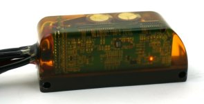
Compact Field Oriented Controller, ASI + Grin, limited run

CKs said:
Hello everyone, who can tell me how to set cruise function?
tks a lot~

Hi CKs, unfortunately the cruise function as with most of the other gazillion perifpheral features of the ASI controller suite are not things that we'll either be playing with or supporting, so I can't really help you with that. Our objective and vision for ebikes is that the controller should be a perfect "slave" device, rather than a master. The controller has a single objective and that is to run the 3 phase motor as well as possible from the command of a single throttle voltage signal. Any functionality like motor thermal rollback, cruise control, pedal torque sensing, power limits, etc. would then be then be the responsibility of human/bike interface device which is sending this throttle signal. There are lots of advantages to this scheme since it decouples the ebike behavior from the specific controller functions, you can swap in and out any controller and still have the same core features.

On that front, I wanted to talk a little bit about the wiring pinout that we decided on for this run of potted Phase Runner :mrgreen: devices. Asides from the battery cable and motor cable, there are just three smaller signal wires coming out of the casing
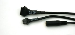
PhaseRunner Cables.jpg

The top of course is a 6-pin Cycle Analyst plug, the middle is a 3-pin throttle plug for those using either no CA or a V2 CA device, and the bottom is the TRS stereo microphone jack for programming via one of the TTL->USB adapter cables.

If you peel back the throttle heathrink, you'll see it's actually a 6 conductor rather than a 3 conductor cable. The two wires for an on/off key switch are soldered together and tucked in the bundle so that the controller is always ON when connected to a battery. But if want to have an on/off controller switch that doesn't need to deal with battery currents, then simply hook it up to these two wires. Then you can turn the controller off and shunt everything down without disconnecting the pack.
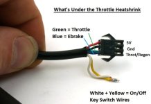
PhaseRunner Throttle Details, sm.jpg

You'll also notice that there are two wires going into the throttle signal line. In this case, we've shorted together the throttle and regen brake lines at the connector pin, and have mapped both signal ranges so that from 1-4V you get accelleration, while from 0-1V you have variable proportional regen. The throttle signal has a 10K pull down to Gnd, while the ebrake signal has a 40K pull-up to 5V. So when these two wires are shorted together like this the signal floats at 1V and has no regen or accelleration. If you prefer a system where you have separate analog inputs for braking and throttling, then you can decouple the wires from the connector and hook things up into two different plugs. If you have an ebrake cutoff lever and want that to activate regen without using a CA3 device, then my recommendation would be to simply hook it up so that it shorts your throttle signal to ground. Sqeeze the brakes, throttle goes to 0V, and you get maximum regen.

Personally, I'm hoping that this idea of a single signal wire being used both for accel + regen catches on, because it facilitates the production of easy bi-directional throttles for proportional regen without adding more sensors and cables to the bike setup. But in case it doesn't, at least it will be possible to revert things to the more conventional scenario of two separate inputs.
 
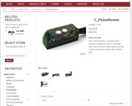
And we're live!
http://www.ebikes.ca/shop/ebike-parts/controllers/c-phaserunner.html
StoreSite.jpg

Thanks guys for all the excellent feedback. In the end we decided to go with Phase Runner for the name on this baby, but those who had name suggestions which made the shortlist I will be contacting to offer discount coupon codes once I figure out how to do that on our site.

I've got a drop-down list so that you can choose whether you want it potted clear, black, or any number of colours. Actually we have more dye colours than listed there, so if you have a really special request (like sparkles! or glow-in-the-dark!) then put it in the comments field during checkout and we'll see what can be accommodated. At the moment we can produce about 2-3pcs / day so I've indicated that there would be a 5-10 day lead time in general. There are in total just over 40 units we'll be able to make, so I've also limited the checkout to just 1 unit per person to make sure they have a chance to get around.

circuit said:
Since you mentioned these, how much is BAC1000 or BAC3000?

This goes back a little while, but we also finally received our shipment of what ended up being a newer BAC2000 device as well. So still 12 fets but 100V capable and with a peak phase amps of 150A, though a fair bit lower than that continuous.
http://www.ebikes.ca/shop/ebike-parts/controllers/c-bac2000.html

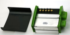
The top cap opens off with large brass terminal blocks for bolting on the phase and battery leads
BAC2000_Open.jpg

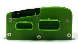
While the signal lines are all done via Molex MX150 series automotive plugs.
BAC2000_End_Sm.jpg

Right now were are just listing them bare bones or with the unterminated molex automotive connectors, since we haven't had a chance to make up any pre-configured cable harnesses yet. But for people who are computer smart and can do all their own wiring, the pinout details are listed here
http://www.accelerated-systems.com/files/20150522_BAC2000-72-100_Datasheet.pdf
And they have both TTL level and RS484 pins available for communications.
 
justin_le said:
I've got a drop-down list so that you can choose whether you want it potted clear, black, or any number of colours.
With such boring names. ;)


But I think PhaseRunner is a good name choice. :)
 
Congratulations on getting this to market! I got my order in as soon as I saw this pop up, so I'm looking forward to tuning 'er up in a couple weeks. I assume software/configuration is essentially the same as what's already been covered in this thread? Just smaller size and more power? :twisted:
 
cycborg said:
Congratulations on getting this to market! I got my order in as soon as I saw this pop up, so I'm looking forward to tuning 'er up in a couple weeks. I assume software/configuration is essentially the same as what's already been covered in this thread? Just smaller size and more power? :twisted:

Yes exactly. Instructions should be followed just as Robbie described in the posts starting here:
http://endless-sphere.com/forums/viewtopic.php?p=978256#p978256
Our next step in this process will involve making a much trimmed down user interface to the controller settings in a manner that is more familiar to people here. No per-unit references and simply set things like max phase amps, max battery amps, max regen amps, max regen voltage, and a few buttons to facilitate the auto-tuning and hall mapping procedures and enabling field weakening. The full bacdoor suite would be available for anyone who wants it, but likely 95% of people will be perfectly served by a much more intuitive and slimmed down setup UI.
 
Scraping the bottom of the barrel here.

FOG - "field of green"

Looks great Justin!
 
johnrobholmes said:
Having more experience than I would like to have potting equipment, I must say that is an absolutely beautiful job! Do you have a vac chamber for degassing prior to the pour, or putting a vac on it during the pour? That is a pretty sizable hunk with no bubbles, fantastic work sir. You make me want to redesign my RC controllers for molded potting, although we are quite spoiled just pouring into the plastic cases these days.

Hey Thanks JRH. We've been degassing after stirring the resins and dye before pouring to get a completely bubble free liquid, but not again after it's in the mold. The trick is always to have it pour slowly injecting the liquid from the bottom up so that it doesn't entrap any new bubbles from the pouring process. That, and using a resin with fairly low mixed viscosity. 1000 cps is nice but < 500 cps is a dream for wetting and flowing around all the small parts.
 
I ordered mine today.... hopefully its nice and smooth, stand up scooters like gopeds are sensitive to jerky starts.. throws you off balance.
really looking forward to it. :mrgreen:
 
so the last two days I've read through this thread a few times.
Im pretty confident on everything except mounting it. Unlike most of you, I am not using it on a bicycle, instead I am using it on a scooter.
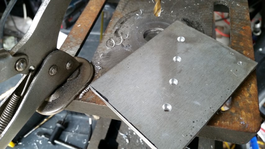
I have to mount it on an aluminum plate... thing is, the bolt holes go out the side, so I cant just bolt it to the plate. Now I supposed I could drill and tap the base, but I dont think thats best for warranty reasons. lol.
So far the only idea I have is to stick some metal pins through the holes, then use some kind of clamp on them. but I dont like that idea very much. I want to be sure its firmly and solidly on the heatsink, as I plan to use it at 100% capacity all the time. (20ah of 16s lipo and theres no pedal-assisting on a scooter)

This is how I mounted my previous controller:
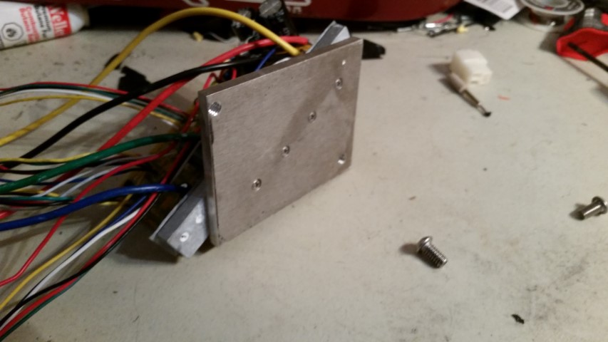
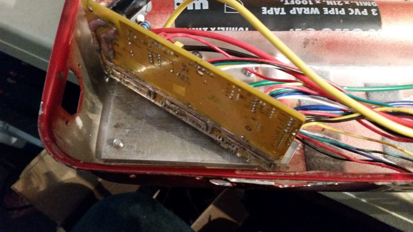
20150404_111654.jpg

20150404_133536.jpg

20150404_134413.jpg

(not shown is the plastic spacer that supports the card)

In my setup, the entire scooter pan is aluminum and makes a ok heatsink. The idea is the plate takes the heat from the controller, acts like a decent thermal spreader to the pan, and the pan is in the airflow.


what I would like to do for this controller, is somehow mount it to the plate (with some thermal paste in between) and then mount the plate to the scooter (also with some thermal paste) but I cant figure out how to do about doing that.

anyone have some decent ideas?
 
Another thought....

Is it possible to have another power connection on the board so that the CA shunt can measure charging as regen. I just remembered I do this on my current board, and with this encapsulated, I wont be able to add one for myself... or does this have this ability already?
 
MrDude_1 said:
so the last two days I've read through this thread a few times.
Im pretty confident on everything except mounting it. Unlike most of you, I am not using it on a bicycle, instead I am using it on a scooter.
I have to mount it on an aluminum plate... thing is, the bolt holes go out the side, so I cant just bolt it to the plate. Now I supposed I could drill and tap the base, but I dont think thats best for warranty reasons. lol.

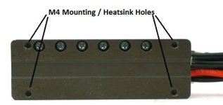
Hey MrDude, no need to break out your own drill and tap set, we've already got four threaded M4 holes in the bottom of the heatspreader plate. We had intended these mostly for the use of bolting on a larger finned heatink extrusion for those who want to push higher sustained power levels, but they'll work just as well for mounting holes too.
HeatsinkHoles.jpg

I'll have a full CAD diagram prepared and uploaded later today with this detail and the other relevant dimensions too so that people who aren't simply zap strapping the controller to their frame tubes can know what to expect mechanically.

MrDude_1 said:
Another thought....
Is it possible to have another power connection on the board so that the CA shunt can measure charging as regen. I just remembered I do this on my current board, and with this encapsulated, I wont be able to add one for myself... or does this have this ability already?

That's a good point to raise which I hadn't considered. How many amps do you need to charge at? In this particular layout we have the shunt wired so that S+ is the Gnd of the PCB, while S- is brought out to the battery lead. So if you combined both the existing throttle and CA ground wires and used this as the ground return for the charger you'd be able to handle at least 3-4 amps of current. But for more than this we can easily do a one-off pour that brings out an additional separate wire for your charger ground which would be more ideal.
 
justin_le said:
MrDude_1 said:
Another thought....
Is it possible to have another power connection on the board so that the CA shunt can measure charging as regen. I just remembered I do this on my current board, and with this encapsulated, I wont be able to add one for myself... or does this have this ability already?

That's a good point to raise which I hadn't considered. How many amps do you need to charge at? In this particular layout we have the shunt wired so that S+ is the Gnd of the PCB, while S- is brought out to the battery lead. So if you combined both the existing throttle and CA ground wires and used this as the ground return for the charger you'd be able to handle at least 3-4 amps of current. But for more than this we can easily do a one-off pour that brings out an additional separate wire for your charger ground which would be more ideal.

I have added power cables to the controller side of the shunt not only for recording charging as regen (occasionally a quick, high-power charge) but so that current draw of accessories can be accounted for on the CA. I would like to see a high current S+ connection available.
 
amberwolf said:
but ya know you gotta try making one cast in amber (not just cuz of the name ;) but cuz it's both pretty and there's another name to go with it that *maybe* some people would grok:

Well Amberworlf, you had your wish. One of the orders that came through shortly after posting these on our site was for an Amber colour device so we got to see how that turned out, and here is your focsil to behold:
AmberPour2.jpg
AmberPour.jpg

Otherwise though everyone else has been on the clear bandwagon.

On that front, for people who saw that the devices were showing as "Sold Out" on the website, basically I'm trying to avoid having any backlog build up beyond the published 5-10 day lead time before shipping and have been doling them into inventory accordingly. The production seems to be going fairly smooth overall and so every day I'm adding another 2 units to the store website (as I've just done right now). If it shows as sold out then simply wait a day and there should be a couple more available again.
 
mrbill said:
I have added power cables to the controller side of the shunt not only for recording charging as regen (occasionally a quick, high-power charge) but so that current draw of accessories can be accounted for on the CA. I would like to see a high current S+ connection available.

OK, two is enough to make this a thing. I've added an additional option to the checkout process to have us include an additional ground wire located on the + side of the shunt.
ExtraWireOption.jpg

If someone has already made a purchase and really needs this extra wire tap then send an email so we can make note.
 
justin_le said:
Well Amberworlf, you had your wish. One of the orders that came through shortly after posting these on our site was for an Amber colour device so we got to see how that turned out, and here is your focsil to behold:

I like it. Still clear enough to see the insides. Can you stick a little dinosaur inside with the board?

The tapped holes on the heat spreader look good. I think with some silicone and some basic brackets it would transfer heat well to a frame tube.
 
justin_le said:
Hey MrDude, no need to break out your own drill and tap set, we've already got four threaded M4 holes in the bottom of the heatspreader plate. We had intended these mostly for the use of bolting on a larger finned heatink extrusion for those who want to push higher sustained power levels, but they'll work just as well for mounting holes too.

I'll have a full CAD diagram prepared and uploaded later today with this detail and the other relevant dimensions too so that people who aren't simply zap strapping the controller to their frame tubes can know what to expect mechanically.
Awesome news. I never saw anything about holes on the "bottom" so I didnt think there was anything there.

justin_le said:
That's a good point to raise which I hadn't considered. How many amps do you need to charge at? In this particular layout we have the shunt wired so that S+ is the Gnd of the PCB, while S- is brought out to the battery lead. So if you combined both the existing throttle and CA ground wires and used this as the ground return for the charger you'd be able to handle at least 3-4 amps of current. But for more than this we can easily do a one-off pour that brings out an additional separate wire for your charger ground which would be more ideal.
I often stuff in 20 amps at 66v... If you could bring out another separate wire to do that, it would be an excellent option. It would let me continue to use the CA to measure charging... just be sure to label what wire is what. :lol:
My Invoice Number is 10000333... the one for Travis F in Charleston, SC... if I need to be more specific than that, I want to meet whomever is in my town doing this. lol.
 
fechter said:
I like it. Still clear enough to see the insides. Can you stick a little dinosaur inside with the board?

I thought it was a trapped mosquito we want, then market them as having dinosaur DNA inside!

The tapped holes on the heat spreader look good. I think with some silicone and some basic brackets it would transfer heat well to a frame tube.

I'm not quite sure what the transfer rate will be like to tubing just with zip ties, but yeah with a more form fitting bracket it could be quite effective. This is one of the other tests that we'll be putting our wind tunnel and thermal camera to good use for.

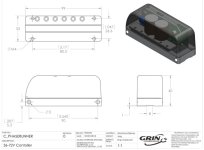
Anyways, here are the exact hole locations and dimensional diagram as promised. The side holes are 90mm apart, while the four bottom holes are on a rectangle 80.5mm x 26.6mm
PhaseRunDims.jpg

And the link to the .pdf copy is here
http://www.ebikes.ca/documents/PhaseRunner_Dims.pdf
 
justin_le said:
amberwolf said:
but ya know you gotta try making one cast in amber (not just cuz of the name ;) but cuz it's both pretty and there's another name to go with it that *maybe* some people would grok:

Well Amberworlf, you had your wish. One of the orders that came through shortly after posting these on our site was for an Amber colour device so we got to see how that turned out
Hah, if that's the only one, I guess it must be mine! I figured that the amber color would be a suitable hommage to amber as the all-time classic potting material - not ideal in terms of workability or curing time, but with no competition for durability. :wink:
 
justin_le said:
circuit said:
Since you mentioned these, how much is BAC1000 or BAC3000?

This goes back a little while, but we also finally received our shipment of what ended up being a newer BAC2000 device as well. So still 12 fets but 100V capable and with a peak phase amps of 150A, though a fair bit lower than that continuous.
http://www.ebikes.ca/shop/ebike-parts/controllers/c-bac2000.html

The top cap opens off with large brass terminal blocks for bolting on the phase and battery leads
View attachment 1

While the signal lines are all done via Molex MX150 series automotive plugs.


Right now were are just listing them bare bones or with the unterminated molex automotive connectors, since we haven't had a chance to make up any pre-configured cable harnesses yet. But for people who are computer smart and can do all their own wiring, the pinout details are listed here
http://www.accelerated-systems.com/files/20150522_BAC2000-72-100_Datasheet.pdf
And they have both TTL level and RS484 pins available for communications.

Just got one of these for work, looking at ways to control it using a microcontroller. The data sheet mentions a proprietary library for the serial protocol:

Communication to the drive is via a proprietary ASi object dictionary using the ModBus RTU protocol. At the physical layer, RS 485 protocol is standard with options of TTL 232, CAN OPEN or LIN.

Is this object dictionary available/ is there documentation somewhere for it?
 
I have one more small question.
I will be using the on/off switch.
Does it carry battery power or a lower voltage?
If it is battery power, what is the max power I can pull through this wire?

I was thinking of using the wire to power my dc-dc converter for my lights. If this wont work, I can connect via the CA plug, but I prefer to not modify that unless needed...
 
MrDude_1 said:
I have one more small question.
I will be using the on/off switch.
Does it carry battery power or a lower voltage?

It's battery power
If it is battery power, what is the max power I can pull through this wire?

It will be dealing with the controller's current draw (few 10's of mA) plus the Cycle Analyst and whatever CA accessories you have plugged in.

I was thinking of using the wire to power my dc-dc converter for my lights. If this wont work, I can connect via the CA plug, but I prefer to not modify that unless needed...
Connecting via the CA plug makes the most sense for sure since then it will automatically be picked up by the CA so you'll see the power draw of your lights on the screen.
Otherwise, you could pull this from the V+ going to the switch, and then have your ground return on the independent charger ground wire, but the wiring won't be as neat and tidy as just pulling this from the CA.

Justin
(PS, just made another two available via the website. Excited that we have some red and blue potted devices in the order stream)
 
I ordered one of these as soon as they became available! I also ordered one of these thinking I'd use it to program the controller, but now I'm not so sure that's what that hardware does. Is the 'CA-USB' the right tool for working with the controller through BacDoor?
 
toolbag said:
I ordered one of these as soon as they became available! I also ordered one of these thinking I'd use it to program the controller, but now I'm not so sure that's what that hardware does. Is the 'CA-USB' the right tool for working with the controller through BacDoor?

Yup totally. Anyone who already has a CA3 or a Satiator will have this USB->TTL cable on hand already so there's no need to get another one. But if you don't have any means of generated TTL level serial signals from your computer into a TRS jack, then you'll definitely need to pick up the programming cable too. The controllers will not work or will work very poorly if you just plug them into a random motor without doing all the motor tuning steps via software.
 
I'm currently working on another project, but I'm thinking for later this fall or winter to give one of these ASI-based controllers (Phase Runner or BAC2000) a go on my bikes.

Although I've been generally happy with my Lyen and Grinfineon controllers (12-FET models), I've decided a further improvement I'd like to make would be smoother and quieter operation with both my geared and DD systems and a bit more flexibility than an on/off button when using on-demand regen with the DD motor. At the same time I don't want to give up capability or reliability that I currently enjoy with the Lyen/Grinfineon controller.

Questions:

1) Will either of these controllers easily drive one of the newer Nine Continents (cassette freehub model) motors such as the M3006RC?

2) Has anyone successfully configured an old BMC600 scooter motor (kv around 125-130) to run off either of these controllers? This is the motor that was made available for a time that went by the name, "Powerpack", and also appears as fetcher's E-S avatar. It is generally considered to be a difficult motor to drive, and I still have trouble getting a Lyen MKII or an older Grinfineon to drive it smoothly under conditions that involve a low throttle setting with a moderate to heavy load, especially at voltages higher than 30. Phase resistance is around 35 mOhm, and I suspect inductance is also on the low side, although I have not measured it.

http://mrbill.homeip.net/albums/mac_bmc_600w_motor/index.html

3) Do motors and drivetrains (in the case of geared motors) run more quietly with these controllers than they do with a Grinfineon controller, for example?

4) Does the Phase Runner offer Hall signals? If not, would this be a problem for a clutched and geared motor such as the above?

5) With a Lyen MKII controller I've found that the BMC600 produces increasing torque up to a battery current limit of 55A with a phase current limit of 110A (although in practice I limit battery current at the CAV3 to 45A). Which of these controllers would be better suited to this current limit?

6) Is Grin planning to do any customization (potting, Grin-compatible wiring, documentation, etc.) of the C_BAC2000 controller, making that controller a little closer to turn-key (e.g. plug-in replacement for a Grinfineon controller), or are buyers on their own?

7) Can either of these controllers be run off a 7s LiPo battery (24 volts nominal, 20-30 volts actual)? I can run with 14s LiPo (40-60 volts actual), but I prefer to run at the lower voltage (with the geared motor) since I use my batteries as parallel modules to fine-tune capacity, and I have more configuration options at 7s, such as running an odd number of batteries in parallel.

8) What range of on-demand (as opposed to "natural" or "passive" regen due to high speed) regeneration current can one expect from these controllers? Is there a feature to prevent wheel lock-up (like an anti-lock brake) if user inadvertently requests too much regen?

9) Should I be looking at any other controllers besides those offered by Grin?

Thanks.
 
justin_le said:
The controllers will not work or will work very poorly if you just plug them into a random motor without doing all the motor tuning steps via software.
As I proved to myself today with the original version, at the end of this post:
http://www.endless-sphere.com/forums/viewtopic.php?f=2&t=67833&p=1078210#p1078210
:oops:
 
Back
Top