CKs said:Hello everyone, who can tell me how to set cruise function?
tks a lot~
Hi CKs, unfortunately the cruise function as with most of the other gazillion perifpheral features of the ASI controller suite are not things that we'll either be playing with or supporting, so I can't really help you with that. Our objective and vision for ebikes is that the controller should be a perfect "slave" device, rather than a master. The controller has a single objective and that is to run the 3 phase motor as well as possible from the command of a single throttle voltage signal. Any functionality like motor thermal rollback, cruise control, pedal torque sensing, power limits, etc. would then be then be the responsibility of human/bike interface device which is sending this throttle signal. There are lots of advantages to this scheme since it decouples the ebike behavior from the specific controller functions, you can swap in and out any controller and still have the same core features.
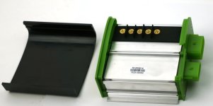
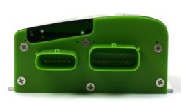
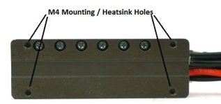
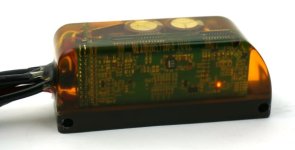
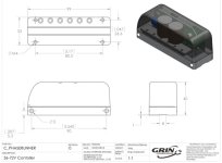
On that front, I wanted to talk a little bit about the wiring pinout that we decided on for this run of potted Phase Runner
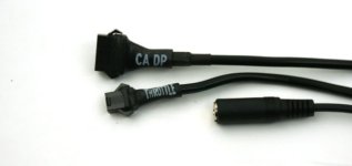
The top of course is a 6-pin Cycle Analyst plug, the middle is a 3-pin throttle plug for those using either no CA or a V2 CA device, and the bottom is the TRS stereo microphone jack for programming via one of the TTL->USB adapter cables.
If you peel back the throttle heathrink, you'll see it's actually a 6 conductor rather than a 3 conductor cable. The two wires for an on/off key switch are soldered together and tucked in the bundle so that the controller is always ON when connected to a battery. But if want to have an on/off controller switch that doesn't need to deal with battery currents, then simply hook it up to these two wires. Then you can turn the controller off and shunt everything down without disconnecting the pack.
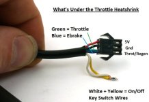
You'll also notice that there are two wires going into the throttle signal line. In this case, we've shorted together the throttle and regen brake lines at the connector pin, and have mapped both signal ranges so that from 1-4V you get accelleration, while from 0-1V you have variable proportional regen. The throttle signal has a 10K pull down to Gnd, while the ebrake signal has a 40K pull-up to 5V. So when these two wires are shorted together like this the signal floats at 1V and has no regen or accelleration. If you prefer a system where you have separate analog inputs for braking and throttling, then you can decouple the wires from the connector and hook things up into two different plugs. If you have an ebrake cutoff lever and want that to activate regen without using a CA3 device, then my recommendation would be to simply hook it up so that it shorts your throttle signal to ground. Sqeeze the brakes, throttle goes to 0V, and you get maximum regen.
Personally, I'm hoping that this idea of a single signal wire being used both for accel + regen catches on, because it facilitates the production of easy bi-directional throttles for proportional regen without adding more sensors and cables to the bike setup. But in case it doesn't, at least it will be possible to revert things to the more conventional scenario of two separate inputs.


