• Hello ES! We could use some help to get us past the finish line on building the new knowledgebase for the forum.
    Can you donate? Please see our fundraising page. Thank you!

Controller / Calibration issues

OnYaBike

New here
Joined
Dec 8, 2025
Messages
10
Location
Australia
Hi

I have just fitted a new conversion kit by Elemex, an Australian brand. Specs are 250w rear hub motor, 48v with a 15A Smart Sinewave controller, a UKC1 display and a KT-V12L PAS sensor. Reaching out to Elemex has produced zip.
Three issues:
1. Speed calibration is way out. By changing the weel size setting from 26" to 14" the speed is near correct.
2. The suggested poles setting for PAS is 8 which doesn't work but 12 poles does.
3. Setting the max speed setting to 25kph has the motor cutting out too early so can barely reach 25kph. I am running the max speed set to 38kph which means I can run up to 28kph. Our local regs require a max of 25kph with PAS and no throttle. I don't not have the throttle connected.
The controller has the Elemex brand when it starts. My understanding is access via the USB is only available through some dealers.
the controller being Smart Sinewave controller - does that mena it can be accessed via bluetooth and a phone app?
Any suggestions that can resolve the above would be appreciated.
Thanks
 
Does your bike have a geared hub motor? Do you know its reduction ratio? I had to set the motor magnets to reflect the ratio 100 to 130 depending on the display for the s866/s869 series. My H8 display (Which I am using now) has a percentage setting for the gear reduction This helps zero in the speed without the wheel setting..which helps the speed limit power problem for me anyway. It would reduce power too much when approaching limit even with throttle. Montana has a 20 MPH limit
 
Last edited:
Hi

I have just fitted a new conversion kit by Elemex, an Australian brand. Specs are 250w rear hub motor, 48v with a 15A Smart Sinewave controller, a UKC1 display and a KT-V12L PAS sensor. Reaching out to Elemex has produced zip.
Three issues:
1. Speed calibration is way out. By changing the weel size setting from 26" to 14" the speed is near correct.
2. The suggested poles setting for PAS is 8 which doesn't work but 12 poles does.
3. Setting the max speed setting to 25kph has the motor cutting out too early so can barely reach 25kph. I am running the max speed set to 38kph which means I can run up to 28kph. Our local regs require a max of 25kph with PAS and no throttle. I don't not have the throttle connected.
The controller has the Elemex brand when it starts. My understanding is access via the USB is only available through some dealers.
the controller being Smart Sinewave controller - does that mena it can be accessed via bluetooth and a phone app?
Any suggestions that can resolve the above would be appreciated.
Thanks
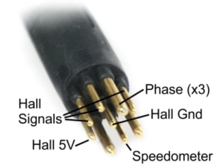
Can you post a pic of the motor’s connector with the pins clearly visible?
 
Hi

I have just fitted a new conversion kit by Elemex, an Australian brand. Specs are 250w rear hub motor, 48v with a 15A Smart Sinewave controller, a UKC1 display and a KT-V12L PAS sensor. Reaching out to Elemex has produced zip.
Three issues:
1. Speed calibration is way out. By changing the weel size setting from 26" to 14" the speed is near correct.
What is the actual wheel size?

What is the number of poles of the motor?
Is there any gearing inside the motor? If so, what ratio is it?
You'll need those two things to set most controllers' speedometer up.

If the motor has a separate speed sensor on the shell (inside) *and* your controller can read that sensor (some don't, and only use the motor halls for this, in which case you need the previous data), then you need to know how many magnets the cover has on it inside. This can be six, or one, or anything in between, typically, but usually one. (cuz there's six spots but builders are cheap and won't spend more than they *have* to.


How far off is your speed from reality? What is the ratio?
You can use that to change the number of poles or whatever setting your controller has for it's speed sensor per it's manual.


2. The suggested poles setting for PAS is 8 which doesn't work but 12 poles does.
How many magnets on the PAS sensor ring?
 
Does your bike have a geared hub motor? Do you know its reduction ratio? I had to set the motor magnets to reflect the ratio 100 to 130 depending on the display for the s866/s869 series. My H8 display (Which I am using now) has a percentage setting for the gear reduction This helps zero in the speed without the wheel setting..which helps the speed limit power problem for me anyway. It would reduce power too much when approaching limit even with throttle. Montana has a 20 MPH limit
Yes, the motor is a brushless geared motor. I will have to find out the gear reduction. One thing I overlooked is the 'Poles in Motor' setting under advanced settings. The default setting was 46. Should be 1 or 6. 6 doesn't work. 1 works fine. I have reverted the wheel setting to 26" and the displayed speed is about right. The only issue remaining is the max speed setting. Its apparent that the max speed is a function or % of the PAS setting. If the max speeed is set at 25kph, I can only achieve 25kph using PAS 5. If I use PAS 2 its around 18 kph. The sweet spot for me is using PAS 2 and cadence of 60-70 and cruise at 25 kph. I can only do that if the max speed is set 35 kph. Obvisously I what to max by battery range hence not wishing to rely on PAS 5.
 
What is the actual wheel size?

What is the number of poles of the motor?
Is there any gearing inside the motor? If so, what ratio is it?
You'll need those two things to set most controllers' speedometer up.

If the motor has a separate speed sensor on the shell (inside) *and* your controller can read that sensor (some don't, and only use the motor halls for this, in which case you need the previous data), then you need to know how many magnets the cover has on it inside. This can be six, or one, or anything in between, typically, but usually one. (cuz there's six spots but builders are cheap and won't spend more than they *have* to.


How far off is your speed from reality? What is the ratio?
You can use that to change the number of poles or whatever setting your controller has for it's speed sensor per it's manual.


How many magnets on the PAS sensor ring?
Wheel size 26". I have set poles in motor to 1 and it has corrected the speed issue. I opened a PAS sensor and counted 6 magnets. On the net somewhere I found that a KT-V12L PAS sensor has 12 poles and it works on that setting. The motor is a geared motor but I don't know the ratio without opening it to take a look. I will see if the supplier will tell me. The only issue now is the max speed setting and its relationship to the PAS setting. See previous reply above.
 
Thanks. A geared hub motor requires an internal speed sensor in order to provide a speed signal to the controller. The signal is provided by a sixth conductor, usually white. If the above represents the motor connector from the motor, and not the controller side connector, then it’s pretty unusual to be missing the additional conductor. Without the separate signal, the controller will use a hall signal for speed, but won’t register when coasting.
 
Thanks. A geared hub motor requires an internal speed sensor in order to provide a speed signal to the controller. The signal is provided by a sixth conductor, usually white. If the above represents the motor connector from the motor, and not the controller side connector, then it’s pretty unusual to be missing the additional conductor. Without the separate signal, the controller will use a hall signal for speed, but won’t register when coasting.
Yes, thats what is happening. Stop pedalling and the speed displayed stops.
 
If speed only displays *while pedalling*, whether or not the motor is running, then that means the PAS sensor is connected to your speed sensor input of the controller.

If it displays only while pedalling *because the motor is running*, then it's correclty connected to the PAS input of the controlller, but the controller is not set to read the shell speed sensor in the motor (1 or 6 poles) and is instead set to read the hall sensors of the motor (number of magnets x the gearing for pole count).
 
If speed only displays *while pedalling*, whether or not the motor is running, then that means the PAS sensor is connected to your speed sensor input of the controller.

If it displays only while pedalling *because the motor is running*, then it's correclty connected to the PAS input of the controlller, but the controller is not set to read the shell speed sensor in the motor (1 or 6 poles) and is instead set to read the hall sensors of the motor (number of magnets x the gearing for pole count).
Yes, speed displays while pedalling because motor is running.
 
Sorry, I have given you incorrect info. The above pic I copied from the UKC1 user manual. The motor has a 9 pin male connector. The controller has a 9 pin femail connector for the motor and a 9 pin connector for the display, on/off, brakes and throttle.
Back to my original question:
Can you post a pic of the motor’s connector with the pins clearly visible?
 
It's odd that the controller appears to be taking the speed reading from the internal motor speed sensor when powered, but drops the speed reading when coasting. I would check the motor speed sensor manually, using a multimeter, a 5V source and the 10k resistor. With the motor disconnected, applying 5V (in series with the 10k resistor) and ground, and measuring the voltage between ground and the speed output, while rotating the motor, you should see the signal alternating between 5V and 0V. If it does, the motor speed sensor is functioning properly, and eliminates that as a potential cause as being the speed sensor itself. It would also indicate that the controller is using the hall sensor input for speed when coasting for some reason since the displayed speed is dropping to zero.
1765392934051.png

The controller on their website is dual mode, so operates both in sensored and sensorless mode. Maybe it's switching to sensorless when off throttle for something. Can you confirm that you ran the self-learning routine when you first set it up?
 
Last edited:
You mentioned the UKC1 display, so I looked it up.


I was looking to see if there is a setting for the number of magnets in the speed sensor. As many Bafang hubmotors use six and most others use 1, this is a necessary setting for a respectable controller,. Should look for a setting that allows 0 thru 6, On many of these controllers, setting this to zero means there is no speed sensor, and the controller must use the speed calculated when motor is running,

Looks like Assist poles is the closest match, which allows 0 thru 12. Is it set to 1?


ukc1.jpg
 
It's odd that the controller appears to be taking the speed reading from the internal motor speed sensor when powered, but drops the speed reading when coasting. I would check the motor speed sensor manually, using a multimeter, a 5V source and the 10k resistor.
I am guessing, looking at how my KT displays work, is that the display will shows the speed based on motor rpm, using the gear ratio and wheel diameter to calculate speed. When coasting, they flip over to the speed sensor. If the speed sensor is broke, then they show nothing. It is possible to disable the speed sensor input too. Hence my above post.

Why don't they always use the speed sensors? It seem stupid that they don't, but I think the first controller designer did it in the above fashion, and all subsequent controller designers copied the flow charts.
 
You mentioned the UKC1 display, so I looked it up.


I was looking to see if there is a setting for the number of magnets in the speed sensor. As many Bafang hubmotors use six and most others use 1, this is a necessary setting for a respectable controller,. Should look for a setting that allows 0 thru 6, On many of these controllers, setting this to zero means there is no speed sensor, and the controller must use the speed calculated when motor is running,

Looks like Assist poles is the closest match, which allows 0 thru 12. Is it set to 1?


View attachment 381982
Poles in Motor is set to 1.
The Assist Poles is set at 12.
The default settings in the pic above didnt work.
 
It's odd that the controller appears to be taking the speed reading from the internal motor speed sensor when powered, but drops the speed reading when coasting. I would check the motor speed sensor manually, using a multimeter, a 5V source and the 10k resistor. With the motor disconnected, applying 5V (in series with the 10k resistor) and ground, and measuring the voltage between ground and the speed output, while rotating the motor, you should see the signal alternating between 5V and 0V. If it does, the motor speed sensor is functioning properly, and eliminates that as a potential cause as being the speed sensor itself. It would also indicate that the controller is using the hall sensor input for speed when coasting for some reason since the displayed speed is dropping to zero.
View attachment 381973

The controller on their website is dual mode, so operates both in sensored and sensorless mode. Maybe it's switching to sensorless when off throttle for something. Can you confirm that you ran the self-learning routine when you first set it up?
No, I did not run any self-learning mode. I wasn't aware of this until you mentioned. Not was it in the 3 different user manuals I have for the kit set up. The only reference I have found is in an advert for the same type of UKC1 display.
What is the self learning plug????

These were the instructions.
1. How shall I match my motor for first time use? (Very Important)
(Please check Controller Connection Diagram and Manual, Page 1)
1). Lift your motor wheel off ground (very important)
2). Connect Self-learning plug 6-8 seconds
3). You will see motor wheel rotate slowly

Since yesterday the only change I made was to disconnect the 2 connector plugs from the controller to take the photo I posted for you. The whole thing was disconnected for 5-6 hrs. Today I have been for a ride and would you believe it, the speedo is displaying the actual speed even when not pedaling. First time I have seen that in the 3 weeks since I fitted the kit.


4). Please check whether rotation direction is correct
(a). If correct direction, then keep 6-8 seconds, then disconnect
(b). If reverse direction, then disconnect and plug again till get correct rotation direction, then keep 6-8 seconds, then disconnect
5). Motor and Controller Pairing finished!
 
Back
Top