converting meanwell power suply into Lipo charger

Indeed I got you confused with that statement... The diode connects to the top of the middle winding, while the FETs (the line running down) connect to the bottom of the topmost winding (and not to the diode). The connections cross and are not connected except via the capacitor. Hope this clarifies.
 
OK, I drew up a few sketches about how to mod the NES-350-48 (should also work on other voltage versions) for current control
and for permanent FAN ON or remote fan control.
If you need a 12V supply then you can tap into the fan supply, but note that it is referenced to the negative side of the 48V output and do not overload this supply or you lose both the fan and the over-temperature protection!

Current control should allow turning the current down from the max specified to zero if you add a 5k (or 10K) potmeter across the 2.5V reference SHR1 next to the 8-pin U100 and connect the wiper of the pot to R134 instead of R134 directly connected to SHR1. The current through R134 controls the output current limit.
The SHR1 reference voltage (2.5V) is also used to set the output voltage, so do not overload this reference or the output voltage will go down.
You can set a lower current limit permanently without the potmeter by simply adding another resistor between R134 and SHR1. The value of R134 is 3k3 so adding a 1k resistor will reduce the current by some 25% while adding another 3k3 resistor will give you half the output current.
Currentcontrolschematic.jpg


The fan control can either be a permanent ON which only requires you to connect the E and the C pins of Q150. This can be done with a short wire or a drop of solder. You can go fancier and make the fan remote control with either a switch or even an opto-coupler, for example if you want to control more than one NES which are in series, so their negative outputs are not the same level. you can add an opto to each NES and connect the LEDs to the same switch and power supply so you can control them together. SHR2 sets the reference level to turn the fan on, so the remote control can simply connect across this device to drive Q150 under remote control.
Fancontrolschematic.jpg


Here is how it looks at the bottom of the PCB - where to make the mods:
NES-350-48PCBbackcentercontrol-1.jpg
 
Outstanding! That makes it easy.

I know some guys just put a pot in series with the current sensing (R134 equivalent) on the older ones to lower the current limit. It won't go all the way to zero and is non-linear, but only takes two wires to hook up, so may be a good alternate. I'd guess around 5k might give a nice useful range.
 
Latest schematic

Still a few questions, but here it is as far as I have got. it is all of Cor's drawing, just the missing bits to fill in


Still a few un connected components..not sure where they connect to, suspect the out put of transformer...Cap, Diode and resistor..common at one end to the 48 volt out...the other end I have not found got them anywhere yet.
 
Hear is the latest.

Have done near on 14 hrs on this today.

If you spot any mistakes, let me know

Schematic deleted from here and moved to

http://endless-sphere.com/forums/viewtopic.php?f=14&t=36114

so i only have to keep one thread up to date with the schematic
 
Hi Neil,
Wow! What a dedication! Let me go through the questions you sent me:

The transformer winding numbers are quite arbitrary, I did not take the transformer apart, I do not even know the direction of winding although I could measure all that as soon as I have the supply working.

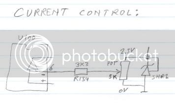
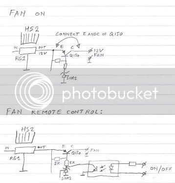
SHR2 is identical to SHR1, both are AZ431 voltage references (2.5V). You can think of them as a zener diode with a control pin or as a regulator. The control pin is compared to the internal 2.5V reference and if the control input is lower then the device does not conduct, if the control pin is higher than 2.5V then the device does conduct.

From the 48V positive, a line runs downward passing by R122 and then into a diode. The other side of the diode does not connect to U100 pin 6 but only to the 3k3 resistor that feeds pin 8 (power supply), The line from pin 6 crosses and does not connect to the diode and the 3k3 resistor.

The two paralleled switching FETs are N-channel.

The current shunt J100 in the negative 48V line is missing, it is located between the 3 680uF elcos and the 5k6 bleeder resistor.

RTH1 and relay: this circuit looks perfect, the value of the resistor is 510 Ohms (sorry for my crappy handwriting).
The cap below it with the question marks is a safety and EMI reducing cap between the rectified AC negative and the secondary (48V) negative. Value is 2n2 250V~. The other side of the cap and the SVR1 top connection must connect to the -48V output near the LED, because where it connects now is at the wrong side of the current shunt J100.

Resistors R100 and R101 are 39 Ohms - again a case of my handwriting....
Note that L100 connects directly to the bottom of the lower secondary winding. The R101 and C101 are a snubber from the diode output to the negative 48V line (the bottom of the lower secondary winding)

The resistor feeding the base of Q5 and ZD2 is 3k9 in value (3.9 kOhm)

The pair of resistors from the Source of the switching FETs to negative supply, R56 and R both have value 0.22 Ohm. The reference nr of the other resistor is R57.

The two switching FETs are called Q1 and Q2. The 5.1 Ohm gate resistors are R10 for Q1 and R12 for Q2. The zener diode protecting the gate drive is called ZD1 (not ZN1) and the resistor parallel to the zener has value 5k1, I made a mistake in my sketch.

The marking that ended up under L100 is actually meant to be a voltage level indication at the junction of L100 and R127, here the voltage can get as low as -59mV at maximum current (voltage drop across the J100 shunt)

I think that is it - much less changes than I expected, you have done a wonderful job of capturing the schematic from the hand-drawn sketch that I sent you, thanks for all your hard work! Now people will be able to fix their NES if it blows up, mod them because they understand how it works and in general a lot more people will be happy with their NES because it can now be used just as easily as the 'S' series.
At the same time I do not think that Meanwell will have a problem with this schematic, even though it is an effort of reverse engineering, I deliberately left a few unimportant components off the drawing and most caps do not have their value noted down, so you can't build this power supply from the schematic - so the effect will be that the NES will be sold *more*, not less.
 
I have started a new thread decicated to the NES supply..if not for now..it will be easier to find in future via the forum search function


Reply to the above is in the new thread, along with an update to the schematic.

Oh BTW..not so much your handwriting as small letters..scanning, transmission, then viewing on screen..plus my eyes and cultural differences..You are from Europe originally yes? I see this a lot with work colleagues..the shapes of letters..such as 9 7 and 4 all seem to be taught slightly different in Europe compared to british system


http://endless-sphere.com/forums/viewtopic.php?f=14&t=36114


I'll go through the schematic again in light of your answers and post an update in that thread above.

If anyone else fancies doing any..let me know and I'll send the the latest sch file
 
fechter said:
I know some guys just put a pot in series with the current sensing (R134 equivalent) on the older ones to lower the current limit. It won't go all the way to zero and is non-linear, but only takes two wires to hook up, so may be a good alternate. I'd guess around 5k might give a nice useful range.
Hi Richard,
Yes, that is a way, an even easier mod if you just want a lower (below 100% load) limit is to increase R134 by about 30% and test the new limit, adapt the resistor if the limit is off, since it depends on tolerances in the shunt and the soldering and length of the traces.

What I was curious about - you told earlier that you have a charge control board that you add to the 'S' series to allow turning the charger down/off. It connects to the "OVP" point in the voltage feedback divider.
Does your control board pull that point up (like having a FET pulling it towards the 48V supply)? Because that would work on just about any supply, as they typically have a feedback voltage divider that gives 2.5V at the configured output voltage. That will essentially work everywhere, as long as you can located the feedback divider (usually the potmeter at the front of the unit). If you also need to control the current then it becomes a different ball of wax for the NES.
 
Cor, funny you should ask that.
As I was going off to sleep last night, I was contemplating getting up and posting the same thing, about finding out where on the NES we could tie Richards board in to one of these supplies
Until Richard comes in to comment, here is a link to his thread about the board (s)

http://www.endless-sphere.com/forums/viewtopic.php?f=31&t=21768

As you scroll through the thread, around page 10 you will see mention of a second type of board from Gary at tppacks. This one had three pots, and did more than just limit current. Richard seems to think..and he should know, that there were issues with this board type, but I am not sure what they were. But I have two of the three pot boards in regular daily use and they both work fine, but I am not suing them for current limiting. I do the SVR2 current mod on the S- series Meanwell and use the 3 pot board just for its other function.

The other function to my mind is more useful than the current limiting function, simply because, if someone is capable of buying the board, and the components, to build it and then successfully get it working, they are more than capable of doing the current mod on the Meanwell it self. Adding an external board to do what the Meanwell can do itself is just complicating things without adding functionality.

These other function of the three pot board that i talk about is:
Monitoring the output current of the Meanwell, and when it drops below a certain presettable threshold (pot 2), changing an indicator LED from Orange to Green, then forcing the output voltage to drop by a pre settable amount (pot3) and effectively shutting down charge current to the battery.

This end of charge shut down and indication to me is more useful than the current limiting function
 
NeilP said:
This end of charge shut down and indication to me is more useful than the current limiting function

On my NES-350-48 with it's trimmed shunt, when the current drops to 20ma it audibly clicks "off" and current ceases to flow. The led stays green though.

I generally charge with a turnigy watt meter inline so I know when it's "swicthed off".
 
NeilP said:
Cor, funny you should ask that.
As I was going off to sleep last night, I was contemplating getting up and posting the same thing, about finding out where on the NES we could tie Richards board in to one of these supplies
I checked Richard's board schematic and it indeed pulls the voltage control feedback point to positive, thereby lowering the output voltage of the supply.
The board should in theory work normally on a NES and tying to the OVP point next to the LED. Don't know why it would be a problem on the NES.
 
I know how SMPSs work (sort of), but can anyone explan how can MW clone S-350-36 heat up less at 37V@8A than at 37V@5A? Specifically, switching transistors temperature is what I'm checking. I've noticed that at 8A it's buzzing much less than at 5A, so I guess transistors are changing states at lower frequency, so that's why they're heating up less.

Does this make any sense?
 
The less time the parts spend in their linear regions, rather than just being on or off, the cooler they tend to stay, as a general rule.
 
Thanks for the info :)
 
frodus said:
I'd invest in a GOOD CHARGER, one that charges with a smart profile. Anything else is just asking for trouble.

Any recommendations. So far, in my looking, with virtually no personal experience using a smart charger (for multiple types of batteries, is the Revolectrix Powerlab 8 (http://www.revolectrix.com/pl8_description_tab.htm ). What charger do you use?

Unboxing:
http://www.youtube.com/watch?v=-J3MxpjjIIY

Review:
http://www.youtube.com/watch?v=05sgCnDaDkQ
 
I just got may hands on a used meanwell 3000 48 http://www.powergatellc.com/mean-well-rsp-3000-48-power-supply, but just now realize according the manufacture spec sheet it is rated for 180-264VAC input.

I really want to use this one with a fechter limiting board as an "opportunity" charger when on the road, which means I would like to run 110 volts.

It is not 3 phase so should take one leg of power...what happens if i try to run 110 volts through it with a fechter limiting board to dial it down per breaker limitations?
 
please, tell me overload protect , over temperature protect and overvoltage protect on meanwell power supply s350-48
thank very much!!!
 
Green Machine said:
I just got may hands on a used meanwell 3000 48 http://www.powergatellc.com/mean-well-rsp-3000-48-power-supply, but just now realize according the manufacture spec sheet it is rated for 180-264VAC input.

I really want to use this one with a fechter limiting board as an "opportunity" charger when on the road, which means I would like to run 110 volts.

It is not 3 phase so should take one leg of power...what happens if i try to run 110 volts through it with a fechter limiting board to dial it down per breaker limitations?


It wont run at all. PFC will stay in low voltage shutdown mode.
 
Dang this is an old thread! :lol:

DrkAngel: Ah! Read your threads; especially appreciated the S-350-48 8)

Here’s all that I know:

Generally speaking: The trick when stringing two or more chargers of differing voltages together in series is that the output is driven by the one with the lowest current. I found out through experience that it was pointless to try to parallel PSUs that were not designed to be paralleled. Don't try to make a silk purse out of a sow's ear; purchase quality equipment that designed for the rated job. If you're dead-set to parallel, take a look at the MW RSP series. The Terminal Blocks on these MWs are IMO light duty; best to use spade or ring terminations.

I'm still using the HRP-600 assembly for my 63V system, and it's been steady-on dependable since 2011 when I began driving 2WD. :wink:
Charged, KF
 
Unless you are desperate to try converting a Meanwell, or have a box of them spare / cheap, I'd say the days of meanwell conversions are gone...at least for me any how.

There are now plenty of ready to go SMPSu's available from the likes of BMSBattery, EM3EV, etc...

Some people have very bad things to say about BSM battery and have had bad experiences...they sell cheap supplies..but their shipping is extortionate. When ever I have had a question, they have always been back at me with an answer..not within hours, but certainly within the week. My guess is that they only have a certain number of fluent english speaking staff, so all the e-mails get handled when they are at work. I have 4...maybe 5 BMS chargers..and all work jsut great..from a small plasrtic case 250 Watt one all the way up to the 2kW unit.

order higher voltage than you need and turn it down a bit.
If you are not sure which pot is which, take a photo, label it Pot A Pot B etc..and send them an e-mail..they will get back to you with what pot does what.
Note what voltage and current it is set to when you receive it...work out the Wattage rating...(amps multiplied by volts).

Now any adjustments you make...make the wattage ratign of your new settings the same as or less than how they shipped it to you .

Always buy a higher voltage unit than you need and reduce it a bit.. NEVER adjust voltages up, unless you are 110%sure the components inside are designed for the higher voltages...but even then...cheap chinese supplies liek this...de rate them and they do last well.


http://endless-sphere.com/forums/viewtopic.php?f=14&t=38284

compare how many Meanwells you woudl need to make one of these:
http://www.bmsbattery.com/alloy-shell/29-alloy-shell-1200w-lifepo4li-ionlead-acid-battery-ev-charger.html
 
overload protect and overvoltage protect,how to action on meanwell power supply s350-27v??
 
Back
Top