DIY (Mini) ebike/moped -> square tube frame, hoverboard motors - does this look reasonable? Any obvious oversights?

ziddan

100 mW
Joined
Mar 4, 2025
Messages
36
Location
Sweden
Hello all!

Ive started collecting parts/planning for my first (mini) ebike/moped project and am looking for some input on the build.

An overview of my intent with this:
Fun of building.
And cruising, ive enjoyed old two stroke mopeds and a relatively new kit addon motorized bicycle.
Best case is that this project will let me commute about 16km/10 miles each way to and from work with comparatively little maintenance.
Setting the limits of the controller to 25km/h and a just enough amps to get there, for good range rather than racing.

Parts already collected:
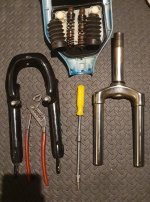
The bicycle coil spring fork+head tube pictured below is one currently part of a bicycle ive picked up and will be widening the forks on to fit the fatter tire, the bit sticking into the frame in the pic will obviously not be there.
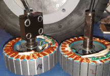
2x350w hoverboard motors bolted together, holes drilled, rim side adapters printed, just need the front rim to arrive so i can figure out how much to space the individual motors from each other so both tires will have the same profile.
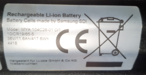
2x36v 11ah batteries ive got for 50 bucks each, said to be unused which i can believe as there is not a scratch on the locating pins, the slots where the locking latches go or the connectors, will be switching out the connectors to XT60.
13 x 5.00-6 4pr tires specced for 30km/h and 200 kilograms.

Parts in the mail:
Front rim, brace disc and callipers.
1000w Brushless ebike speed controller with display (for configuration of speed and amp limts) and a thumb throttle, box goes inside the frame in front of the seat, display possibly also there, throttle as usual on the handlebars.

Parts yet to be gotten:
Seat, ill cut out the base from some plywood, shape it in foam to then stretch and staple leather or vinyl over it, its going to be the full length of the rear flat where the bicycle saddle is still visible in my reference image.
Front/rear lights and side reflexes, ill find something cheap and easy.
Probably tallish handlebars for a relaxed riding position.
Need to figure out a front axle, probably allthread and spacers as seems common on DIY minibikes.

And then onto the frame:

r/minibikes - DIY square tube frame, does this look reasonable? Any obvious oversights?
Ill be getting 3x2m lengths of 30mm square and 1x2m length of 25mm square tubing, both with 1.5mm walls

Two 30mm of which will have wedges cut in it to bend into the shape pictured, minus the front upright, totalling 1.88m each.

The third 30mm x 2m tube will be cut into the two front upright 435mm parts and leftovers will be used to widen the fork.
This should also leave enough for the foot rests, which im thinking will be a single bar that bolts on at the lower end of the front, as well as someplace else along the side or bottom for compact stowage for when the whole thing is put into the back of my car or whatever.

Im not 100% sure how wide i need to space the two sides yet as im still waiting for the front rim, ive got a measurement for the front rim itself. 122mm wide, but the seller doesnt give the hub width/outside of bearing to outside of the other bearing.
But thats not much of an issue as ill have a bit to do before ive get that far,

Whatever the distance i will be cutting the 25mm tubing to length for joining the two main parts of the frame at each bend.
Along with two or so extras under the seat for ease of mounting it+the batteries.
A brace above of and in front of the rear wheel for putting on a rear light and a fender.
A couple of braces along the bottom, perhaps for storage inside the frame?
A brace in the front where the diagonals join the upright to mount a blanking plate to protect the inside of the frame from unnecessary road dirt.

Im not a great welder but i can booger stuff together and will be putting in gussets at the main corners of the frame.

Am i going overkill? Am i going way light? Have i missed anything obvious?

-Thanks :)
 
The bicycle coil spring fork+head tube pictured below is one currently part of a bicycle ive picked up and will be widening the forks on to fit the fatter tire,
Which fork is it? (many are not worth using, and some that are have aluminum crowns that would be tough to weld (so you'd have to remove the crown and make a new one unless you can weld it and re-heat-treat it).


2x350w hoverboard motors bolted together, holes drilled, rim side adapters printed,

Printed?

Would be interesting to see the whole dual-motor-sandwich idea, parts, and process. Not many people try this; last one I recall was years ago where Farfle paired two magicpie stators and rewound them to be a single one; a different process from yours most likely.


2x36v 11ah batteries ive got for 50 bucks each, said to be unused which i can believe as there is not a scratch on the locating pins, the slots where the locking latches go or the connectors, will be switching out the connectors to XT60.

Which batteries? (even if unused, it doesn't mean they'l support your intended usage, or that they are any good. we have seen a lot of "junk" around here. ;) ).


1000w Brushless ebike speed controller with display (for configuration of speed and amp limts) and a thumb throttle, box goes inside the frame in front of the seat, display possibly also there, throttle as usual on the handlebars.

Note that if you are using those two motors with one controller, you'll want to ensure the stators and rotors are correclty locked together as pairs to be synchronized***, and then parallel the phase wires. If the controller is not sensorless, then you will use only one set of halls, from one of the motors. (you can keep the others ready to connect as a spare set).

***one way to do this is get the stators bolted together, but not hte rotors, then parallel the phase wires and run a small current thru one pair, and the field will align the rotors, at which point you can bolt them together.


And then onto the frame:
I recommend a diagonal from one front corner to one rear corner, preferably from the steerer top front corner to the dropout botton rear corner, to stiffen the frame. Unless you need the frame to be open for larger cargo access, these can be welded in place. If you need them to move out of the way for cargo access, you can use a quick-release-lever nut at one end of one of them (with it's bolt welded into the frame corner it attaches to), and a hinge at the ohter end of the same one, with the other side's diagonal welded in place.


Also: How do you plan to get the rear wheel in and out of hte frame, with the axle above the lower frame members? And what kind of dropouts do you have planned? I'd recommend pinching/clamping dropouts (there's a lot of examples around the forum, including some secure-but-ugly ones on my SB Cruiser).


Im not a great welder but i can booger stuff together and will be putting in gussets at the main corners of the frame.
As long as your welds are secure (full penetration, good fill, etc), and you're not welding incompatible materials, etc., you should be good. See my SB Cruiser, CrazyBike2, Mk IV / V trailer, etc threads for examples of not-great-welding that has still worked. :oops:
 
Which fork is it? (many are not worth using, and some that are have aluminum crowns that would be tough to weld (so you'd have to remove the crown and make a new one unless you can weld it and re-heat-treat it).

No idea, looks like the most common cheap ones :p
Ive checked that the parts are magnetic which should mean that they are something that i should be able to weld to.

Printed?

Would be interesting to see the whole dual-motor-sandwich idea, parts, and process.

Im using the files put out by Nicholas Cardoza.

Which batteries?
Even if they arent the best i hope that they will get me going, at 100 for two when they usually go for around 300 each im hoping that it cant be too bad of a deal. The bikes (Lyfco brand) they fit got the top score in some tests done by one of our (Swedish) national news papers.
Apparently the seller is friends with a guy that used to run some electronic and random stuff shop that was pretty big for a while but it recently closed down and the seller was invited to pick through stuff at their office before everything was binned.
1741551035529.png
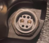
With this output connector, i read up on it and its only rated for 10A so even if i had a male of those id still be switching over to XT60.
1741551088997.png
And a barrel jack for charging.

Note that if you are using those two motors with one controller, you'll want to ensure the stators and rotors are correclty locked together as pairs to be synchronized***, and then parallel the phase wires. If the controller is not sensorless, then you will use only one set of halls, from one of the motors. (you can keep the others ready to connect as a spare set).

***one way to do this is get the stators bolted together, but not hte rotors, then parallel the phase wires and run a small current thru one pair, and the field will align the rotors, at which point you can bolt them together.
Thank you, this is exactly the type of info im after!
Ive been doing reading and watching vids up to now with no actual bouncing of ideas against people.

Yeah im going to be running them in parallell with with just one of the sensor leads connected.

a diagonal from one front corner to one rear corner
Right, i was thinking the two smaller diagonals would serve to stiffen the two near vertical tubes well enough but i can definitely see how one across would strengthen against deformation, that can be sorted easy enough.

How do you plan to get the rear wheel in and out of hte frame, with the axle above the lower frame members?
A very good question :D
I must have been thinking of this like a minibike build due to watching quite a few of those and absorbed that the axle is put through the rear wheel when its already in the frame, which, now that you pointed it out, obviously isnt how this is going to work.
I guess the easy way out would be mounting the axle at the bottom or back of the frame for simplicity.
Bottom seems like the more secure option as it would minimize shear forces on the bolts.
I might do a Z at in the frame at the back and have the axle sit about centred in the bottom tube there.

And what kind of dropouts do you have planned? I'd recommend pinching/clamping dropouts
I will be re using the clamp ones from out of the hoverboard, the side with the flat comes free when dismounting it from the board, the other is integrated into the chassi of the board and will have to be cut free.
I was thinking i get some longer bolts and make it bolt together through the frame rails as the clampy bits are not magnetic/i probably cant weld them.
1741551991001.png

not-great-welding that has still worked.
Im confident enough that they ought to hold without looking too good :p
Last year i welded two bits of 3mm wall square tubing, feet/fork holes for while transporting, to the bottom of an extension boom for a telehandler and they have held up to the abuse.
As well as adding reinforcing strips to the bottom of excavator/loader buckets without any parts falling off yet, knock on wood.

So revising with your points and my own idea/wish for the look and removability of the rear area/wheel.
What do you think? :)
1741556803049.png

I like your music BTW :)
 
Last edited:
No idea, looks like the most common cheap ones :p
Ive checked that the parts are magnetic which should mean that they are something that i should be able to weld to.
Probably.

The issue with them being the most common cheap ones is that they may not provide useful suspension, though if you are riding well-paved smooth roads it might not matter at the low speed range of 25km/h or less.

Another issue is that the cheapest ones have a lot of slop in them, and can wiggle back and forth a lot, during braking / acceleration. Even the Suntour ones I've had a few of had that problem, though to a lesser extent than the noname ones and cheaper ones. One Suntour (XCM? XCV?) I had was pretty good, as far as that goes (though I broke the aluminum crown in the only collision I've ever had...I keep meaning to make a new crown to reuse the stanchions....

Some of the *really* cheap steel ones have a crown that I wouldn't even trust for a pedal bike with a small light rider; I used to have one that I had intended to use on a lowrider bent (taht I never ended up building) but found that wehn it was placed under a load that flexed it "forward" (by the angle it would've been at on the bike) teh crown twisted enough that I was afraid it would collapse and fail.... :shock: I think I ended up cutting the brake boss U frame off the fork and discarding the rest, using that frame on my good Suntour fork to have dual caliper brakes (front and rear).... (and even that U frame bent enough in braking to make those less useful than they could've been).

But if you're replacing the crown with your own anyway, then as long as your crown is better than that, at leat you won't have that worry. ;) Still may have a lot of slop in the stanchion bushings, though.


Im using the files put out by Nicholas Cardoza.
Thanks for linking that--looks useful for assorted adaptations (with possible modifications to fit different applications).


Even if they arent the best i hope that they will get me going, at 100 for two when they usually go for around 300 each im hoping that it cant be too bad of a deal. The bikes (Lyfco brand) they fit got the top score in some tests done by one of our (Swedish) national news papers.
Apparently the seller is friends with a guy that used to run some electronic and random stuff shop that was pretty big for a while but it recently closed down and the seller was invited to pick through stuff at their office before everything was binned.
Hopefully they;'ll work out.

I guess the question then is...how old are they, long were they just sitting unused, which cells it uses, and what it's really designed to handle. You'll find out how well they perform when you test them out, but something you can check for is how much voltage sag there is under load.

If there are issues with shutdowns under load, you can try leaving the packs on the charger until the charger stops cycling on and off (can take hours, days, or longer) to ensure they're at least balanced (but this doesn't "fix" the issues that cause imbalance and pack shutdown).


With this output connector, i read up on it and its only rated for 10A so even if i had a male of those id still be switching over to XT60.
Keep in mind that if a low-current connector was used, the pack may not be capable of a higher current than that--either the cells, BMS, or internal wiring and interconnects may be limited to below the connector rating. If it has a fuse, that rating will give you an idea of the best the pack is expected to be able to survive; typically it would be rated for quite a bit higher than anything it would normally see.


Right, i was thinking the two smaller diagonals would serve to stiffen the two near vertical tubes well enough but i can definitely see how one across would strengthen against deformation, that can be sorted easy enough.
Anytime you have a shape, you can divide it into triangles to strengthen it. Any non-triangle shape can fold at it's corners. A triangle cannot. :)


I must have been thinking of this like a minibike build due to watching quite a few of those and absorbed that the axle is put through the rear wheel when its already in the frame, which, now that you pointed it out, obviously isnt how this is going to work.
YOu can rebuild the motors so that it does work that way, but it's a fair bit more work. You'd need a collar tube in the stators, tehn a way to pin the axle to the collar once it's inserted. That can be a woodruff key, or a cotter pin, set screw, etc.

To secure the axle to the dropouts, you can still use the pinching/clamping dropouts.

Checkout Farfle's dual magicpie for possible methods:

I guess the easy way out would be mounting the axle at the bottom or back of the frame for simplicity.
Bottom seems like the more secure option as it would minimize shear forces on the bolts.
Those forces would be the same either way. The difference is the forces on the frame itself. From underneath the dropouts are just pushing up on the frame tubing, but from behind they're pushing on the tubing at the top and pulling at it on the bottom. Dependign on how they're secured to the frame, that may make no difference....


I will be re using the clamp ones from out of the hoverboard, the side with the flat comes free when dismounting it from the board, the other is integrated into the chassi of the board and will have to be cut free.
I was thinking i get some longer bolts and make it bolt together through the frame rails as the clampy bits are not magnetic/i probably cant weld them.
That will probably work. You may also be able to use U-bolts to pass over the frame to secure them.


So revising with your points and my own idea/wish for the look and removability of the rear area/wheel.
What do you think? :)
That should probably work. FWIW, I don't think you need the shorter triangle in the front, with the long full triangulation, assuming the rest of that front is just a "box".

If you feel like it, there are some free FEMM tools out there to see where the stress points are in a frame, so you can correct them. I keep meaning to try them out but haven't gotten around to it (I really should, given the loads I put on stuff).


I like your music BTW :)
Thanks! Which one(s) did you listen to? (i'm always looking for feedback; don't get much; I have a thread for the "studio" stuff if you're interested in the technical side of it).
 
This thread may also be helpful
 
But if you're replacing the crown with your own anyway, then as long as your crown is better than that, at leat you won't have that worry. ;) Still may have a lot of slop in the stanchion bushings, though.
Im thinking ill be splitting the crown horizontally and welding some of that 30x30 in its place, then splitting the bottom bit to weld onto the 30x30 at the correct spread.
Here is very rough sketch:
1741636640581.png

Thanks for linking that--looks useful for assorted adaptations (with possible modifications to fit different applications).
It seems there are innumerable ways people have re-used hoverboard motors, adding chain sprockets to use them as midframe outrunner, doing tire on tire friction drive, drilling holes in them and stringing them as hub motors in spoked wheels, mounting them with belt pullies to run small milling machines and drill presses etc etc.

Hoverboards seem like one of the cheaper way to get what seems to be very useful brushless motors, i got mine for 40 bucks and at 20 bucks per 350w motor that seems like something of a steal.

Hopefully they;'ll work out.
Yeah.
Keep in mind that if a low-current connector was used, the pack may not be capable of a higher current
They are specced for 250w in the original bike, the controller im getting maxes out at 30a and but has a configurable amp limit, which i intend to be setting at something like the 2x the original limit as im going to be connecting the two packs in parallel, again, hopefully they'll work out :)

YOu can rebuild the motors so that it does work that way, but it's a fair bit more work. You'd need a collar tube in the stators, tehn a way to pin the axle to the collar once it's inserted. That can be a woodruff key, or a cotter pin, set screw, etc.
A fair bit of work and preferably a mill, lathe and hydraulic press, beyond my means, doing the bolt together i linked seems like the simplest way.

Those forces would be the same either way. The difference is the forces on the frame itself. From underneath the dropouts are just pushing up on the frame tubing, but from behind they're pushing on the tubing at the top and pulling at it on the bottom. Dependign on how they're secured to the frame, that may make no difference....
Having the mounts under the frame, per the revised sketch, seems it would take a lot of strain (my fat ass) off the bolts as they are holding the clamps in place against motion, more than resisting stretching, back mounted would be loading them sideways.
Either way i think ill go with this revision.

That will probably work. You may also be able to use U-bolts to pass over the frame to secure them.
That might require finding or bending u-bolts to fit, longer bolts and some fat washers seems like the simpler option, simple and less custom fabrication is something im wanting to go for with this

there are some free FEMM tools
With you on this one, "should" :p

Which one(s) did you listen to?
Gareki and The Silent Uncounted this far, parts gave me some Ozric Tentacles vibes, which i hope will be taken as compliment.
Have tried my hand an playing bass with some friends in a cover band but i dont seem to have the knack/feel for it, i could learn to mechanically play the songs with them and we did a few local gigs but they all eventually stopped having the time to dedicate,
when they stopped i did too because i was doing it because i enjoy their company, whatever we were up to.

Personally i started off listening to my dads 60/70ies rock and my moms 70/80ies pop.
Spun off on my own into mostly new wave of british heavy metal/and related through my teens.
Expanding to include psychedelic rock in my early twenties.
Then adding some psytrance/related EDM to it in my late twenties.
Through my thirties ive mostly coasted back on heavy metal with sprinkles of the others mention, tho in latter years i find myself listening to quite a bit of retrowave.

Over more than a decade i used to spend about of a month each summer camping, hanging, drinking, dancing, rocking and tripping out at various festivals but its been a few years since i last went to one.

I checked your studio thread, that tech and skills is outside of my world but what i did grasp was that you like oldtech that does what its supposed to, while disliking stupid software licensing and updates that break stuff. That we can agree on.
 
Last edited:
Im thinking ill be splitting the crown horizontally and welding some of that 30x30 in its place, then splitting the bottom bit to weld onto the 30x30 at the correct spread.
Sounds like an awful amount of work for a fork of potentially unknown quality. I'd make really sure i want to use its internals, otherwise i'd look for a ready-made wide fork. They are really affordable for fat variants nowadays.
 
Sounds like an awful amount of work for a fork of potentially unknown quality. I'd make really sure i want to use its internals, otherwise i'd look for a ready-made wide fork. They are really affordable for fat variants nowadays.
Ive had a quick look and but that didnt turn up any that will accept the 5 inch wide tire without almost doubling what ive put towards this project and most seem to be too tall as well so would need further modification.

As for the qualities of the forks i have, they dont wiggle/feel sloppy when i try to move around with the brake locked, are smooth enough when i compress them and also the fact that i already have them :p

I might look some more if the ones i have dont work out but for now ill go ahead an not spend on that.
 
If they don't wiggle and the smoothly compress then you';ve already got something a cut above most of the cheap forks out there. ;) Might even be sometehing comparable to the decentish Suntour XC-whatever I broke (though mine hasd aluminum crown).


Im thinking ill be splitting the crown horizontally and welding some of that 30x30 in its place, then splitting the bottom bit to weld onto the 30x30 at the correct spread.
Here is very rough sketch:
If the box in that image is a section of square tube, at minimum you'll need to close the ends off, but even then it's possible for it to deform from the vertical and back-and-forth forces on it's walls and top/bottom.

If it weren't your front fork I'd say just try the experiment, but if it does fail suddenly that could be catastrophic and I wouldn't want to be the rider. :(

If the metal is hard enough and thick enough walls, it may be fine. If not....

Structurally it might be better to remove the whole existing crown, then put a hole for the steer tube thru the entire box tube top to bottom, and weld the steerer to both top and bottom walls. Then do the same for each stanchion on each end of hte box tube. then the front and back walls of the tube aren't taking the load like the version you've got there, that's done by the steerer and stanchions themselves.


For narrow forks on OTS (old ten speed) bikes I've seen what amounts to a box (usualy open-bottom) crown, Google Search but even as narrow as they are there's still some twisting of the crown on some of these forks between the steerer and the blades during hard braking.

When I was considering making a fatbike fork out of my old stanchions from the broken Suntour, I was going to cut a stack of steel plates, drill the right size holes, and weld them along the edges to make a thick "solid" plate, then core out holes for steerer and stanchions and weld them in, then make a second stack for the top (above the headtube) taht would have bolted or clamped on. Never built because I ended up getting a double-crown clamp set and made a non-suspension fork out of old cromoly bike frame parts ((using two overlapping sizes of tubing, one of which has the same OD as the ID of the other) and sliping the lowers off a crappy not-really-suspension fork ;) over those, and spotwelding welding the lowers to the tubing to give me easy dropouts as a temporary measure that's still in use (never got around to installing the separate dropouts I got later) on SB Cruiser:

Post with some pics right after buidling if interested The SB Cruiser : Amberwolf's 2WD Heavy Cargo Trike & Dog Carrier

This is the fork I had been using, and why it was replaced with a double crown type The SB Cruiser : Amberwolf's 2WD Heavy Cargo Trike & Dog Carrier and this is why I was using the fatbike fork The SB Cruiser : Amberwolf's 2WD Heavy Cargo Trike & Dog Carrier :/


Sorry if I seem to be going on and on about the fork...but I've seen the results of fork failure crashes, and they're usually pretty ugly. :( Don't want that to happen to anyone!


It seems there are innumerable ways people have re-used hoverboard motors, adding chain sprockets to use them as midframe outrunner, doing tire on tire friction drive, drilling holes in them and stringing them as hub motors in spoked wheels, mounting them with belt pullies to run small milling machines and drill presses etc etc.
Hmm....hadn't thought of that last one--I have a crappy HF drill press with a pretty weak induction AC motor.... but I already have assorted ebike hubmotors that would probably work just about as well. Even geared brushed motors from powerchairs; now *there* is enough torque. :)


Hoverboards seem like one of the cheaper way to get what seems to be very useful brushless motors, i got mine for 40 bucks and at 20 bucks per 350w motor that seems like something of a steal.

I see them from time to time at Goodwill for a few bucks, but couldn't think of a use for any of them before that wouldn't be more work than other solutions I already had. I'll have to be more imaginitive...... :) But, I already have a bajillion projects with "high priority" :oops:

Somebody send me the winning lottery ticket so I can retire and have time to do this stuff. :p


They are specced for 250w in the original bike, the controller im getting maxes out at 30a and but has a configurable amp limit, which i intend to be setting at something like the 2x the original limit as im going to be connecting the two packs in parallel, again, hopefully they'll work out :)
Soudns like a plan; guess yo'ull find out. :)


Having the mounts under the frame, per the revised sketch, seems it would take a lot of strain (my fat ass) off the bolts as they are holding the clamps in place against motion, more than resisting stretching, back mounted would be loading them sideways.
Either way i think ill go with this revision.
Probably the easiest.


Gareki and The Silent Uncounted this far, parts gave me some Ozric Tentacles vibes, which i hope will be taken as compliment.
I'd never heard of them, but a quick YT of a few songs finds I like them--thanks for the comparison!

You may also like Just Give Me A Voice in the Lies, Truth, and Assorted Inconveniences album there, and maybe the most recent one It's Probably Nothing, But..... , probalby Neotenous Chordata, maybe In These Amber Days. Possibly others like Less Like A Whisper, The Moon, It Read To Me, And It Was Bright (it's a little odd) and Ookami no Kari no Yume (Wolf's Dream of the Hunt) (odd in a different way).


Have tried my hand an playing bass with some friends in a cover band but i dont seem to have the knack/feel for it, i could learn to mechanically play the songs with them and we did a few local gigs but they all eventually stopped having the time to dedicate,
when they stopped i did too because i was doing it because i enjoy their company, whatever we were up to.

Sounds like when I "roadied" for The Narrow Way back int he 90s around town, was usually fun and I liked their music. Tried to play keyboards with them in a practice session but I can't play realtime well enough and can't play the same thing twice, so....


Personally i started off listening to my dads 60/70ies rock and my moms 70/80ies pop.
Spun off on my own into mostly new wave of british heavy metal/and related through my teens.
Expanding to include psychedelic rock in my early twenties.
Then adding some psytrance/related EDM to it in my late twenties.
Through my thirties ive mostly coasted back on heavy metal with sprinkles of the others mention, tho in latter years i find myself listening to quite a bit of retrowave.
I haven't listened to much of anything, but looking up "retrowave" on wikipedia makes me think you might like a fair bit of the earlier stuff I've made, some of which is in the Uncommon Ground album on the bandcamp site, and some of which is on the older part of my soundclick page.

My first influences were classical music my dad played at full blast (like the 1812 overture) and "heavier" stuff my oldest sister played (the only name I know from album covers she was forbidden to bring home but did anyway was Black Sabbath, but I don't recall any of it other than the distortion sound of the guitars), music from all the scifi shows and movies I watched, and some of the 80s electronic bands, then stuff from Musical Starstreams (yanni, kitaro, cianni, enya, kraftwerk, ray lynch, lots of others I cant remember the names of offhand). Then I finally got my own keyboard at some point around then and not knowing anything about music or how to play I just made noise on the keys....eventually getting to where I am now after I got a computer to help me edit what I "played" in as midi.

I checked your studio thread, that tech and skills is outside of my world but what i did grasp was that you like oldtech that does what its supposed to, while disliking stupid software licensing and updates that break stuff. That we can agree on.
Oh,yeah, that last for sure. :lol:

If just plain hardware stuff (that I can afford) could do what I need to do with it now, I'd probably still be doing it that way. :oops: Hardware I can hack, and fix, and customize....software, not really so much; my brain just doesn't wrap around it well enough.
 
decentish Suntour XC
These ive got are some stock ones that came with this old bike i have, its just straight coils with no adjustment knobby bits, the things in the top holes are just blind plugs to keep dirt out.
Very much like these:

If the metal is hard enough and thick enough walls, it may be fine. If not....
a stack of steel plates
Another hit for "better ideas when bouncing against other people", i was already getting some flat bar for the gussets so i can easily triple some of that up instead of using a bit of box section.
Weld the crown parts to the center plate and with some angle grinder application ill be able to contour the top and bottom plates around the sections of crown.
Then putting a bead along each edge where one part touches another ought to make it pretty solid, way more structural metal than the box section originally envisioned and more compact too.

1741726478786.png

Black Sabbath
They are definitely among the top bands for me, i was lucky enough to be on the barricade when they played their last original lineup tour back in 05. Having watched quite a few recordings of them playing live i realized Ozzy was likely to be splashing buckets of water across the people in the front so brought a small jar and caught a few droplets, it sits on a shelf in my living room ;)

Hardware I can hack, and fix, and customize.

You seem like a DIY kinda guy so might enjoy Look Mum No Computer on youtube, among what he does is analog synth/random instrument hacks and mods (and some animatronics stuff), even though i dont get the all the technical musicality parts i find myself enjoying the builds and the end product music :)

I will be checking out your music recommendations too.
 
Last edited:
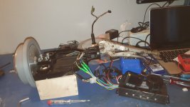
Just fount that my controller with EN06 display has been delivered and decided to have a look at wiring.

It matches the pic on the product page:
1741790059212.png
Phase&hall go to the motor(s), accelerator to the throttle as soon as it gets here, appearance is probably a mistranslation of display as that connector is right, booster ought to be pedal assist and will be unused in my build, self learn is for reversing motor direction.

This leaves me with the following of which im not sure:

The two brake lines, as i understand things, will disable motor power if either is shorted, i suppose one connector for each hand brake, do i have this right?
With the controller powered on they both have +5v
Either way i dont think i will be connecting this as i already have a brake lever that i dont see a reason to replace.

Lamp line, which the display has a matching connector for, i would expect it to toggle a light output at vbatt or 12v from the controller but i dont see one?

I also dont see an output for a rear light.

ADDITION instead of another doublepost:
Found a different place that sells tubing, this time in 6m lengths and hopefully with 3mm (1/8ths) wall thickness, if so i will be doing 25x25 (basically 1") tube instead of 30x30.
I should be able to get both main parts of the frame sides out of one 6m length, going from red circle to red circle byt cutting 3 of the walls and taking out large enough wedges to do the bends.
Then adding in the blue diagonals afterwards.
1741843738006.png
 
Last edited:
Wouldn't it be easier to bend the pipes to form the bends rather than cutting? It seems like that would compromise their strength a lot.
I dont have access to, nor any skill with, a tube bender.

Marking lenghts/cutting wedges is something i can easily do.

A 90 deg bend would have a 90 deg wedge taken out in the direction the bend should go.

The places from where the wedges are cut are in turn bent closed and welded back up.

Most of these bends will also be getting gussets.

I doubt strenght will be an issue.
 
Front rim received and tire mounted, it was a somewhat more gymnastic exercise than i was expecting but now its on there.

Also got the brake disc and callipers, the holes on the disc line up with the mount on the rim so thats good.

As expected the ID of the bearings is 12mm and i was pleasantly surprised to find that there is already a spacer fitted between the bearings.

Hub width is 153mm with the disc mount standing a bit more proud from the rim:
Centerline to outside of rotor mount side bearing: 83.5mm
Centerline to outside of valve side bearing: 69.5mm

So will require a bit of spacer on the valve side, 14ishmm, to get it centred, which was also expected.

Ive also tried putting the rear dual motor wheel together and its looking good, beyond the valve extension i bought leaking so ive ordered a different one to try, hopefully it will hold air and if it does i will be buttoning it up with some threadlocker applied to the bolts/nuts joining the two motors together.

Sadly the weather has gone sub zero (in centigrade) again so i dont feel like being outside and building this weekend, hopefully next week will be better.

ADDITION:
Having, out of self preservation, decided not to try riding the donor hoverboard, i figured it would be a good idea to actually test the motors.

I clamped each in turn to one of the stripped board chassi halves (with some visegrips as a counterweight) and wired them to the controller and found that they do indeed both work.
And while i was quite confident in my measurements (i put in blobs of poster tac with some thin plastic sheeting on top, installed the stator, turned the motor a couple of times and measured the height of the tac), i was still relieved to find that the heads of the bolts that will join them together do no interfere with the windings on the stator.

1742035611860.jpeg

ADDDITION instead of new post:
Took apart the forks as much as i think i have tools for at home to try figuring out some more about them.
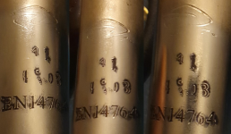
Wasnt much beyond finding they are stamped with a standard, namely 1742062271453.png
Which doesnt tell me much beyond that its up to snuff of some sort as i cant make anything of whats above that EN number :p

ADDITION (one more):
I thought the extendbits i had wouldnt be enough but there was maybe a cm spare when i tried it and ive now gotten the shocks taken apart too, only bits left are the bushings that are held in by spring clips and those i dont feel like removing here at home as they are bound to be really sticky with lube.

Beyond a little surface rust, on non gliding parts, they seem fine.
1742064494211.jpeg

Ill be taking the bushings out when its time to widen the forks since welding would probably melt them, but up until i get there i think the only stuff i can still here at home would be figuring the wiring for lights.
 
Last edited:
Got the forky bits separated, test spaced the wheel centred between them and with room to clear the tire, brake rotor and calliper.

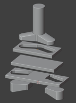
Gonna do up a jig to hold the bits relative to each other using the old brake mounts before i risk welding anything up top and will probably do a second brace at about the height of the old brake mounts for rigidity and easy mounting of a front fender.

The stacks of nuts and washers are just to for figuring this out, ive picked up some pipe that will be cut to correct length spacers.
azvtYvr.jpeg
 
Picked up the tubing for the frame via a quick detour during work today.

As my intent is to cut notches/wedges out of the tubing and bend those closed again for welding to make the frame i figured that i could take the measuring of the actual notches out of the process by doing some homework.

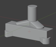
To that end i tried onshape for the first time and made jigs that will slip over the tubing to easily let me mark the different wedges i will be needing to cut out:
KeEUqeG.png


And now they go on the printer :)

And on the topic of printing, i printed off a new half of the rear wheel rim adapter, specifically the one through which the valve extension passes so the tube can be pumped while installed on the frankenrim.
The one i downloaded didnt fit the valve extension i managed to get so i modified it, also made it so that when the tire is installed and the tube is inflated they are going to lock the valve firmly in position, the original had no retention mechanism so it might have wandered back into the rim if one was unlucky..
 
Last edited:
This whole project and thread should be scrapped. You DO NOT rig up wider forks from one crappy fork because you didn’t have the extra $100 for the commercially available one. Front end is something you DO NOT MESS WITH when you don’t know what you’re doing.

This is not a fabrication problem, this is a thinking problem.

You’re taking about a very slow vehicle, but your desired distance to cross makes it serious.

I build CUSTOM to solve problems I cannot by buying a ready made product. Occasionally I will somewhat change a design for a money or time issue, for example rebuilding a battery into a different configuration when it’s around $1000 of my effort.

You’re talking about potentially building a death trap for little to no gain, except that you would trade dozens or hundreds of hours labor for probably less than $5 per hr to find out you still have to buy the stuff and you wasted all that time anyway. Also more importantly it is EXTREMELY UNSAFE!! You don’t have enough experience fabricating anyway… trying to rig up garbage to create more garbage is NOT the way to learn to build things. An experienced fabricator would see it would take more EFFORT and likely COST in designing of good jigs just to make this happen, than to just spend the money on it.

So far you just took a good crappy fork that would have worked for something, and just scrapped it. You will never get it welded with the right alignment to move smoothly ever again without first fabricating heavy strong jigs. Might as well weld it rigid.

It sounds like you need a job working under some pro fabricator to learn the ropes! Cause you obviously want to be building stuff, just learn to do it right with the right mentor.
 
Last edited:
So far you just took a good crappy fork that would have worked for something, and just scrapped it. You will never get it welded with the right alignment to move smoothly ever again without first fabricating heavy strong jigs.
Bold of you to assume a noname elastomer-damped kids fork ever moved smoothly to begin with ;)

I personally agree with the assessment of reasonability of this approach (and have mentioned that way above in the thread), but other than drastically unsafe constructions, we shouldn't be in the business of telling others what and how to build; merely advise. Considering how the vehicle is planned to be used, if the front end snaps it'll likely result more in a funny story than a serious accident - here's to hoping that the OP will keep the uncertain durability characteristics of his build in mind.
 
Considering how the vehicle is planned to be used, if the front end snaps it'll likely result more in a funny story than a serious accident
I’ve gotten hurt worse at 7mph than at 70mph. In fact my worst ever injury was at about 20mph, 2nd worst at 30mph. Safety when it comes to motor vehicles is NOT something to be trifled with. So I’ll ignore what I should or shouldn’t tell people, it’s a free country and if you’re doing something extremely stupid and reckless I’ll be here calling it out. It’s the right thing to do and I’ll risk being called an asshole for it that’s just fine, if it saves a life or person from serious injury.
 
Last edited:
EXTREMELY UNSAFE!!
Noted, just like life in general ;)

Im not all that worried tho, if the fork i get together sucks ill just go the route of welding up a common minibike type fork, just tubing that turns on a bolt through some bushings in a cut to length tube for a headtube.

you need a job working under some pro fabricator
Ive welded some before but asked my boss to show me some tips for doing up these sort of tubes as im new to thinner gauge, there are tube constructed things built by him, with welds older than i am, that we still use at work.

Fiido Q1S
Looks like nice but im quite set on building my own as the process as part of the fun.
 
Notched tubing today before i got too cold, its still around freezing here.

These two should essentially "roll up" into the two main parts of my frame:
mNFgBS7.jpeg


I figure i will try doing that tomorrow, just gotta take some measurements from my drawing and nail a couple of blocks to a pallet as a jig for getting the distances right.
 
I welded up one side yesterday, its strong enough that i can jump on it without it bending at all and the welds hold firm.

Had a couple of blow throughs but filling them in was easy enough, not the most beautiful welds but i got a couple of good ones and cant say im too disappointed in the rest either.

Sadly its a little bit crooked, some of the bends arent confined in plane but i bought enough metal that i can call this first one a learning experience if necessary.

Its likely that i didnt get all the tips of the wedges exactly perpendicular and just a small deviation ought to be making the bends go off center.

Now im just about to head to the garage to have a go at the second one i cut, ill mark a third and grind out a bit more space in the points of the wedges in the second to allow for my inaccuracy before rolling it together.

Ill try cutting the welds on the first, widening the wedge points on it and putting it back together, if it works then it works, if not i have metal to spare and more practice before going on the second and third.

Addition: 2nd one welded up, the extra space in the wedges allowed it to remain flat and three cuts and rewelds got the first flat :)
They didnt turn out identical as there is a few mms of difference in the top tubes but close enough for who its for.
BHbrXQ7.jpeg
 
Last edited:
Sadly its a little bit crooked, some of the bends arent confined in plane b
Isn't that what sledgehammers are for? :p
 
Back
Top