DIY Toroidal Axial Flux PM

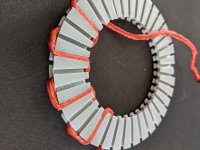
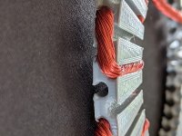
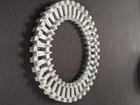
Another attempt at removing more mass. The stator used to be about 45g with the print settings I was using. This one is only 16! and im attempting another that if successful will only be 10g. I like where this is going. Its surprisingly solid too with these current settings (3 walls, 3 top and bottom layers, 50% infill, 0.2mm layer height, no supports, and a 4 line thick brim)

resized-image-Promo (27).jpeg
 
HalbachHero said:
Now I am very curious how close it would have to be to prevent flux leaking, and seeing the difference between the back iron and not is cool, though it complicates how to make this with a printer a bit. I also wonder if on the inner diameter since its basically touching, if flux isn't leaked. Also, what airgap did you use in your simulation? was that with the 11mm?

Sorry I just checked and it was 11mm but I messed up the magnet dimensions (not familiar enough to imperial units) and looking back at it the insert magnet orientation isn't right on top row (leeking more on this side), sorry I shouldn't do this stuff so late at night :roll:
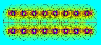
I redid the sim to look at what happen in the center :
hallback _center.PNG
flux_center.PNG

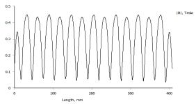
At 11mm the flux is very weak I think, (best case since all magnet are close) it isn't linking well from the two sides. For comparison here is the flux i'm getting with 40x20x5 mm N37 and back iron in my multistator design :

multi_stator.PNG
multistator_value.PNG
(also the coils are at 100/-50/-50 A so it add a little stator flux to the mix but it's not much)

I haven't said that but the plot is the flux at mid airgap (along red line), the value are quite similar to my messed up sims were magnet were 6.4mm thick and airgap at 11mm.

It's not a great news for a lower KV but as I said before the optimal point is rougthly at 2 time magnet thickness, so for 1/8" thick magnet it would mean a 6.35mm airgap (if i haven't miss my conversion again).
At those thickness it is really hard to wind for sure ..
So I guess the thinner you can get it the better.

mxlemming, as pointed by HalbachHero FEMM is a free 2D FEM analysis software for magnetic design, it's really to use and has great tutorials online, you can even get Torque value and get KV from that if you model the coils also.

HalbachHero said:
I like where this is going. Its surprisingly solid too with these current settings (3 walls, 3 top and bottom layers, 50% infill, 0.2mm layer height, no supports, and a 4 line thick brim)

Your 3D printer is working hard for sure ! Another beatiful stator incomming. :thumb:

I was just asking myself, why the big fillet on on side of the tooth ? you might stuff another turn in there I think.
 
Looking nice!

If you made the slots narrow right at the top, you'd have to stuff the wires through the narrow part when winding but it would help keep the copper in place after it was wound. Old-school brushed motors often had "keepers" made of stiff fish paper that slid over the copper and held in place by the rotor teeth. Something like this might work too.

I know the problem of having your windings try to un-wind themselves while you're working on another spot. Anything that can hold the freshly wound coil in place will help. Even tape works for some things and you peel the tape off when finished.
 
Thecoco974 said:
Sorry I just checked and it was 11mm but I messed up the magnet dimensions (not familiar enough to imperial units) and looking back at it the insert magnet orientation isn't right on top row (leeking more on this side)

Good catch, and thanks for redoing it. I also am not a fan of imperial units, unfortunately that's just how they were sold. I think you will be directly responsible for me learning FEMM now :D

I see what you are saying, and I can see the difference between that and your three stator version. The flux lines are not connecting through to the other rotor. One thought though. The stator has a 2mm spot in the middle where the copper does not go. So I wonder if that's sort of how these have been working. I'm going to play around with some simulations and try to understand this better.

Thecoco974 said:
I was just asking myself, why the big fillet on on side of the tooth ? you might stuff another turn in there I think.

My thought here was that given the angle of things the wire wouldn't tuck itself in there nicely, so I was using that spot to add some support for the wire guides to prevent then from snapping off, but I can either try winding it backwards, and keep the support, or remove them entirely to get that precious space back.


fechter said:
If you made the slots narrow right at the top, you'd have to stuff the wires through the narrow part when winding but it would help keep the copper in place after it was wound. Old-school brushed motors often had "keepers" made of stiff fish paper that slid over the copper and held in place by the rotor teeth. Something like this might work too.

all good options. I have definitely seen those paper inserts before, and when/if this turns to metal, I may need something like that to prevent chaffing while winding. Tape might be the quick and dirty solution, but I'm definitely floating the jig idea around.


The 10g version of the stator didn't quite work, one of the wire guides popped off when removing the brim. I guess that's what you get with 1 wall. Anyway, I added 1 more wall, and its looking good! only added 2g, so its sitting at a nice and slim 12g. still need to add the supports on the outside for mounting, but good to know that the inner part can be made so light. If I wasn't redoing my entire bathroom this weekend, id be able to post more. but there's a certain benefit to working from home during the week :wink:
 
This bathroom project has been kicking my butt, but it's getting there. Anyway, I printed a few stators over the weekend, and found that with a 1mm spacing in the middle, it will print rigid enough that you can wind it. Also, I was able to flatten this thing to a thin 6mm in total. and its weighing in at only 8g now. I am also now printing with 100% infill. According to the cross sectional area of each wire guide. I should theoretically be able to fit 6 turns, however. I am only able to achieve 3 before it really becomes difficult. I tried untwisted litz and twisted litz. It's clear that you can fit more wire in a smaller area when its untwisted, but its very difficult to keep thing in place while winding. Even the three turns that I fit on one phase does not stay nicely in its channel.
resized-image-Promo (28).jpeg

I have yet to print a jig, as the stator kept changing, but I think it might be worth trying that now. But until then I will try good old fashioned tape and see where that gets me.
 
Looking good! Thinness will help a lot.

Why all the radial slots? Couldn't you have a continuous plane?

Why so keen to keep it light? You're going to have a few hundred grams of copper and magnets...
 
mxlemming said:
Looking good! Thinness will help a lot.

Why all the radial slots? Couldn't you have a continuous plane?

Why so keen to keep it light? You're going to have a few hundred grams of copper and magnets...

Thanks! I'm hoping so too, but it going to make mounting everything more challenging. I still dont have a good idea of how to do that now. After test winding things, I worry the copper will be in the way.

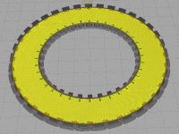
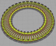
The radial slots are for a couple of reasons. For one it saves material and makes it lighter. Also, (and this might be a limitation of the slicing software I'm using) by making spokes like I did the slicer makes bridges from the inner to the outer edge. These bridges are easier to print then the pattern it chooses otherwise. I have played with settings, but it does not seem to change the pattern of that layer. See the difference here.

As a single plane:
resized-image-Promo (29).jpeg

With spokes:
resized-image-Promo (30).jpeg

Also, I understand that it might be micro optimizing, but I before with a larger stator, the entire motor weighed about 400g. I have already taken off about 35g from the stator, which is nearly 10% of the total weight, and given my understanding of the limitations of my halbach array, I'm hoping to be able to remove a bit more in magnet weight (to be replaced by an iron back, but ill try to keep that minimal). The way I see it is every gram counts. if it was a couple kg, I would be less concerned about the minor improvements, but since its a reasonable percentage, I feel its helpful.

Lastly, I found after winding my test stator, that those slots are helpful for pinching the wire in the slot nicely after the fact. Since you can push it beyond the plane of the stator's middle, you can really mush it in there.
 
I think you're going the right way ! If m'y simulations are correct going from a 11mm airgap to 6.5 will half your kV for the same number of turns. Motors constants are proportionnal to airgap flux.

I may say something stupid, but if you are having trouble keeping the wire in place while winding the next turn can't you do them all at once and terminate them after the fact ? Maybe hard too solder each one with limited space though.


Envoyé de mon Redmi Note 9S en utilisant Tapatalk

 
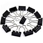
It's hard to judge the size and strength of your stator, but maybe some kind of mini-clips to temporarily hold things in
place?

Mini clips..jpg
 
APL said:
It's hard to judge the size and strength of your stator, but maybe some kind of mini-clips to temporarily hold things in
place?

That's a great idea. I tried it. ( I happened to have a pretty small one) Its certainly helpful for the starting a phase. Before I was wrapping it around a few other wire guides, but then it made doing a lap weird, because you would have to undo it to finish the lap.

I will keep using this. Thanks for the suggestion.


Thecoco974 said:
I think you're going the right way ! If m'y simulations are correct going from a 11mm airgap to 6.5 will half your kV for the same number of turns. Motors constants are proportionnal to airgap flux.

I may say something stupid, but if you are having trouble keeping the wire in place while winding the next turn can't you do them all at once and terminate them after the fact ? Maybe hard too solder each one with limited space though.

I think this is the answer honestly. Before, the reason this was an issue, was because I had a difficult time stripping and soldering all the small strands of wire together close to the stator, and I didnt like the idea of all the extra wire at the end of each lap, but I have acquired a solder pot since I last attempted that and I think that will make it easier, but it will still be a lot of termination points if I fit a lot of laps. I will try this soon, but If I can fit 5 or even all 6 laps, I think it might be worth it.

I am also going to keep playing with the stator a bit, I have had a bit of success with the overhangs I added, but I want to see how far I can take that concept, because it works great for the first lap, but then is essentially ineffective after that.
 
Okay, here's some comparison pictures.

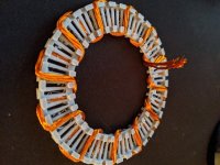
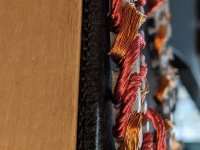
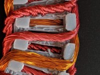
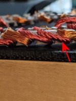
The two photos show the same stator with three sections of phases wound. The more bronze colored wire is 3 laps all the way around in a single piece of wire with untwisted litz (A). To the left of that is 3 segments of litz wire, I untwisted all but the end of three and then twisted all the wires from them together in one (B). Left of that is three twisted litz segments that were again twisted (C).

resized-image-Promo (32).jpeg
resized-image-Promo (31).jpeg

A. I would think this is how a machine would want to do it. Like, to automate manufacturing of one. Because you can use one strip of wire which requires little preprocessing. and there is little waste and nearly zero postprocessing.
B. This worked great. I think this is the way I will try to make this work. Its nicely bundled, and avoids the issue of subsequent wraps overlapping previous ones and becoming a loose mess, which ends up getting pulled out of its slot inevitably. This solution is also scalable. The next test will be with this method, but all 6 if I can fit them.
C. This worked really well. Its almost like the wire wanted to be in the slot the way the contour of the twist worked around the stator, but it uses a lot more wire. As you twist the three strands together you lose a lot of length. The biggest detriment here though is that its not compact, and that method does not scale far beyond three strands.

The issue with B and C, is that you have to cut n number of lengths of wire segments ahead of time, and there's more time spent preparing the wire, and if your math is off you can end up with a lot of wasted wire. However it's pretty easy to figure out using a piece of string too. Also, if you don't have a way of acquiring a bulk amount of litz wire, this could be a more realistic approach anyway, as each segment only needs to be as long as a single lap, which is relatively short. about 65cm in my case.
 
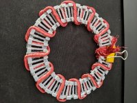
Okay, I think this is definitely the way to wind it. It doesn't fall apart as you go, and it does not as easily get snagged on the stator as your winding. The hardest part with this is getting the length right without being wasteful. I thought I had the right length, and then some, but I was wrong. I will have to make the strands longer next time, but I was able to fit 6 turns! They stick out a bit on top and bottom of the stator, but I think that if all three phases were on it, I could compress and glue it in place.

resized-image-Promo (33).jpeg

I think I can start thinking about how to mount this.
 
I've used paint stripper to clean the enamel off of multi strand ends, if your in a pinch or a tight spot. Harsh chemicals
are no fun, and you have to squirt it and toothbrush it off, but there it is,.. another option. That old solder pot can be
hard to reach sometimes. Not all paint strippers are the same though.

Your stator is looking really good! :thumb:
 
APL said:
I've used paint stripper to clean the enamel off of multi strand ends, if your in a pinch or a tight spot. Harsh chemicals
are no fun, and you have to squirt it and toothbrush it off, but there it is,.. another option. That old solder pot can be
hard to reach sometimes. Not all paint strippers are the same though.

Yeah I have heard of the paint stripper option. I am not a fan of the super caustic chemicals, but really the way I look at it, is the 200C enamel is probably overkill for my stator at the moment given that its plastic, and the easier I can solder it together the better.

I agree the solder pot can be difficult to reach, and I have been running through my head how I will keep things tight after soldering the ends together. It might be a challenge.

On another note. I spend some time learning FEMM and made a handful of simulations that matched my magnet dimensions and using the 6.35mm air gap ( twice the magnet width). I am not trying to argue. But the sims I ran show that the halbach does have some value. Also keep in mind that these sims would be looking at the outside diameter of the rotor, where the halbach is the most spread apart.

Would Thecoco97, any chance you could show me the direction of the poles. You likely had the poles facing the wrong direction on one rotor. I am happy to make my sims available as well, but take a look at this chart I created from the results.
resized-image-Promo (37).jpeg
 
Cool to see you start modeling too !

You will be right to argue in this case :wink: . As I said in a post before I did messed up the hallback insert magnetisation direction on the top row as well as the overall dimensions on my firsts simulations. And after correcting it but with a 11mm airgap the hallback showed improvments but airgap was to big at 11mm showing a lot of flux shortage at rotor center and a weak airgap flux. Here is the magnets orientation in the last simulation result I posted :

magnet_orientation.PNG

Can you post the flux line view and colored density of flux result of your simulation at external diameter ?
 
Thecoco974 said:
Can you post the flux line view and colored density of flux result of your simulation at external diameter ?

At the outer diameter of the rotor, the magnets are spaced about 2mm apart. that's what I used to model this.

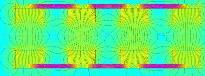
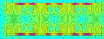
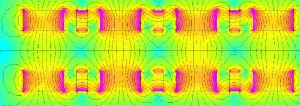
Here are are a few variations
resized-image-Promo (40).jpeg
resized-image-Promo (39).jpeg
resized-image-Promo (38).jpeg

Also I am orienting my magnets the same as you are. So now I am confused. I wonder if it has something to do with the materials I used....

Screenshot 2021-04-23 083231.png
 
On the versions with backiron we can see some flux lines going out at the back, it means the iron is saturated so too thin.
Flux lines are looking good at that airgap with hallback though. You can play with airgap and calculate FOM to optimise it.
You can try at mid and inner diameter to see if it's looking good there too.

Also a little tip I found for having balanced results using this lay flat technique is to split the poles in half at the ends (so mid magnet). Otherwise backiron show saturation near the end throwing all the flux path out of balance.

My last result at twice your actual airgap show what is appening when the flux lines are short-circuiting (don't look at my first simulation post).

Envoyé de mon Redmi Note 9S en utilisant Tapatalk

 
I think for a Halbach array to work well, the magnets need to be touching each other with no gap. This will be challenging in an axial design.

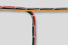
Also, looking at the windings, it seems like twisting them will make each strand longer than they would be if they weren't twisted. If the strands weren't insulated, it wouldn't matter. Of course, no twist is the hardest to wind. Must be a Murphy's Law thing. For untwisted strands, one approach is to lace the wires with thin thread.

Cable Lacing.jpg

A similar approach would be to use a bunch of really short sections of heat shrink tubing along the wire, or a spiral wrapped thread around the bundle. These methods would be a PITA but maybe worth it. I'm sure there are plenty of other variations on these.
 
Thecoco974 said:
On the versions with back iron we can see some flux lines going out at the back, it means the iron is saturated so too thin.
Flux lines are looking good at that airgap with hallback though. You can play with airgap and calculate FOM to optimize it.
You can try at mid and inner diameter to see if it's looking good there too.

Also a little tip I found for having balanced results using this lay flat technique is to split the poles in half at the ends (so mid magnet). Otherwise back iron show saturation near the end throwing all the flux path out of balance.

I see what you are saying about the flux lines leaking out. That makes sense. I played with thickness at 0.5mm intervals, and found 1.5 works as well as 2mm or more (with a halbach). This seems like the minimum I would need to prevent saturation of the back iron. I have yet to play with different materials too. I have been using steel. I am sure that's not the best.

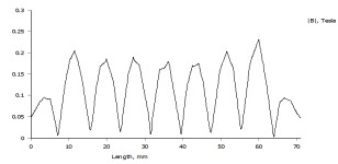
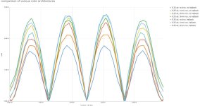
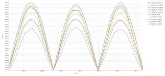
Also I took your advice and used that technique and added more to the series. I re-ran the sims, and re-collected the data. I also cleaned up the ends to just show the middle three bumps.
resized-image-Promo (42).jpeg

The 4 highest lines are all halbach with iron. but there seems to be negligible differences between 1.5 or greater thickness.

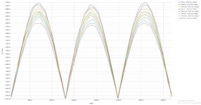
I then went ahead and ran sims for various air cores. Starting with 6.35 then to 6.5 and 0.5mm increments after that up to 8mm. Its clear that the strength is proportional to that height. But the cool thing is, even at 8mm, if I added back iron, it would be much stronger than my mk3 motor was.
resized-image-Promo (43).jpeg


fechter said:
Also, looking at the windings, it seems like twisting them will make each strand longer than they would be if they weren't twisted. If the strands weren't insulated, it wouldn't matter. Of course, no twist is the hardest to wind. Must be a Murphy's Law thing. For untwisted strands, one approach is to lace the wires with thin thread.

A similar approach would be to use a bunch of really short sections of heat shrink tubing along the wire, or a spiral wrapped thread around the bundle. These methods would be a PITA but maybe worth it. I'm sure there are plenty of other variations on these.

I agree it's quite the conundrum. The thread option has been mentioned earlier, and has its perks, but is difficult in its own ways, but I will try it at some point. The heat shrink approach is appealing because If this was ever metal, it may be a good way of avoiding scoring the enamel on the wire, while simultaneously keeping the bundle together through the winding process. Albeit, the heat shrink would add some diameter, to the whole thing, but you could run the wire straight instead of twisted. which has a a benefit of being slightly more compact. That might be a good trade off.

I also modified the shape of the stator. taking a step back from micro optimization, and I added some more mass back to the middle of the circle, As I have been doing these test stators, they keep breaking due to their fragility. This new design does a better job of holding the wire using a flange due to the geometry of the wire guide channels. I also extended the flange on the inner and outer diameter.
resized-image-Promo (45).jpeg
resized-image-Promo (44).jpeg
 
It's some interesting data !
What's look like is happening is that the hallback magnets redirect some of the flux off the back iron decreasing the flux intensity through it and allow a lower thickness before saturation.
Also the insert magnets are adding to the flux in the airgap as you are showing with your graph, but to have a better comparison when removing the insert magnet you could put some wider magnet in place of the current one for identical magnet mass (theorically, in practice the dimension is probably not standard and will require adding Poles/changing rotor diameter).
I actually wonder what it would mean for rotor mass. It would be neat to represent usefull flux against rotor mass and magnet mass in some kind off 3 dimensionnal graph for optimisating our choices.

I've also found in my simulations that flux is more or less proportionnal to airgap.

Your last stator seems to keep the wires neatly in place :thumb: . Do you think it will work without twisting them also ?
 
Thecoco974 said:
It's some interesting data !
What's look like is happening is that the hallback magnets redirect some of the flux off the back iron decreasing the flux intensity through it and allow a lower thickness before saturation.
Also the insert magnets are adding to the flux in the airgap as you are showing with your graph, but to have a better comparison when removing the insert magnet you could put some wider magnet in place of the current one for identical magnet mass (theorically, in practice the dimension is probably not standard and will require adding Poles/changing rotor diameter).
I actually wonder what it would mean for rotor mass. It would be neat to represent usefull flux against rotor mass and magnet mass in some kind off 3 dimensionnal graph for optimisating our choices.

I've also found in my simulations that flux is more or less proportionnal to airgap.

Your last stator seems to keep the wires neatly in place :thumb: . Do you think it will work without twisting them also ?

I was drawing the same conclusion. I will try remodeling the sim, given wider magnets, but due to the inside circumference being tighter than the outer. The magnets can only be made so much wider, but I can certainly try that out. Given that flux is proportional to airgap distance until the poles start to "short circuit", I think its obvious I want to minimize the air gap with the outer limit of that being the "short circuit" threshold, and the inner limit being what is possible to wind.

Also, I like your idea of trying to find an optimal rotor/magnet mass. There would have to be a number of parameters I think, but It seems possible in my head.

And yeah the new stator works really well, though with the wire all in one bundle its quite hard to get it in the channel without bending the stator. Which I was doing, and resulted in another break. I am thinking that I will try the different winding patterns on this stator again, because I also wonder if the straight through wires work on this, that would be lovely.
 
A slight twist in the wires isn't going to increase the resistance too much, but I had real concerns about the one below:

Twisted wires.jpeg

The wire length might be 2x longer than untwisted and I have no idea what the twisting would do to the shape of the magnetic field.
 
fechter said:
The wire length might be 2x longer than untwisted

Oh absolutely, I agree. When I was twisting that one up using a drill. I could see it shrinking. It certainly uses quite a bit more length, and makes a fatter cable.
 
HalbachHero said:
The magnets can only be made so much wider, but I can certainly try that out.

Since I'm not using hallback for my design (yet, because you might be on something interresting) I've always chosen rotor dimensions with the max number of magnets I can fit on the inner diameter. I'm not sure it's the best though. There is still a mystery for me around wich theory apply the best to corelless motor design (Flux linkage/Lorentz Force) and wich flux/coil shape is the best for this application. At first glance every theory should lead to the same result, but who know ?

HalbachHero said:
Also, I like your idea of trying to find an optimal rotor/magnet mass. There would have to be a number of parameters I think, but It seems possible in my head.
I think I've spend at least 80% of my time working on my design geeking about stuff like that and here I am 1 year later and no real prototype at hand :lol: . The only thing preventing me going that far though is the geometry editor of FEMM that is a pain to work with (for me at least), I prefer cading it and import a dxf, but after the fact moving geometry around isn't fast and take to much time. There is also a LUA implementation that permit automatising those thing I guess but I don't have the time to learn that right now. Coming with something usefull will take a lot of data for sure.

HalbachHero said:
And yeah the new stator works really well, though with the wire all in one bundle its quite hard to get it in the channel without bending the stator. Which I was doing, and resulted in another break. I am thinking that I will try the different winding patterns on this stator again, because I also wonder if the straight through wires work on this, that would be lovely.

I was actually thinking that straight winding might be easyer since you can put them few strands at a time in the slot. But they will not stay in place as neatly as your twisted bundle for sure.
Just leaving another tough here : Why not making removable hoverhangs that you can clic in place once the strands are in the slot ? Might be a lot of small and fragile pieces.
 
Thecoco974 said:
Since I'm not using hallback for my design (yet, because you might be on something interresting) I've always chosen rotor dimensions with the max number of magnets I can fit on the inner diameter. I'm not sure it's the best though. There is still a mystery for me around wich theory apply the best to corelless motor design (Flux linkage/Lorentz Force) and wich flux/coil shape is the best for this application. At first glance every theory should lead to the same result, but who know ?

yeah I'm not quite sure either. I thought there was a relationship that worked nicely with the 9 teeth and 12 pole axial flux motors but I have 36 teeth and 24 poles and it has been working. Down the road. I will experiment with that. But I think I need to nail down the stator first.

Thecoco974 said:
There is also a LUA implementation that permit automatising those thing I guess but I don't have the time to learn that right now.

You're reading my mind. I was laying in bed thinking about this the other night. You could show a pseudo 3D image by integrating over the radius of an axial flux motor. I imagine kind of like an MRI. multiple images of a 2D cross section over a distance, and you could construct a 3D image from that. As a software engineer, that has had me thinking quite a bit. I don't know LUA yet, but not knowing something hasn't stopped me yet.

Thecoco974 said:
I was actually thinking that straight winding might be easyer since you can put them few strands at a time in the slot. But they will not stay in place as neatly as your twisted bundle for sure.

I agree. Still haven't tried it but that's up next. I'll report back soon.

Thecoco974 said:
Just leaving another tough here : Why not making removable hoverhangs that you can clic in place once the strands are in the slot ? Might be a lot of small and fragile pieces.

This could be a great Idea that I haven't considered. It could be easy to print those complex shapes, but I think it would only have benefit if laying all of one phase in one lap (i.e. soldering the wires together at the ends). But if the current geometry allows for winding a single wire, multiple laps, then I would prefer that route. Need to test!
 
Back
Top