DIY Toroidal Axial Flux PM

HalbachHero said:
yeah I'm not quite sure either. I thought there was a relationship that worked nicely with the 9 teeth and 12 pole axial flux motors but I have 36 teeth and 24 poles and it has been working. Down the road. I will experiment with that. But I think I need to nail down the stator first.

Actually I think number of teeth (stator poles) vs rotor pole is easy for coreless design, i'm pretty sure we can just go with the number of stator poles equal to rotor poles. For traditionnal steel core design it's actyally a big thing, trying to limit cogging torque with overlapping pôles, but also a compromise because doing that not all the teeth contribute equally to torque and reduce overall efficiency. My concerns are more on the coil shape vs magnetic field shape and efficiency related to those changes.

HalbachHero said:
You could show a pseudo 3D image by integrating over the radius of an axial flux motor. I imagine kind of like an MRI. multiple images of a 2D cross section over a distance, and you could construct a 3D image from that. As a software engineer, that has had me thinking quite a bit. I don't know LUA yet, but not knowing something hasn't stopped me yet.

We are actually thinking at the same thing for sure. I'm really curious at seeing the 3D flux plot but software that can do it aren't really affordable. But more than just flux line actually, outputting the torque constant/Kv more accuratly than just by extrapolating values at midline would be a really big thing for us designing motors.
I don't know if you have played with that yet, but coils can also be added to FEMM (with actual diameter/number of strands/number of turn) and in our case the simulation output the Force in X plane giving the torque value (admitting that the correct value is added in the depth setting of the simulation), power loss can also be outputed.
Having a complete motor design simulation outputing efficiency plot/power curve might actually be possible at the expense of a lot of LUA programation. But to my understanding LUA is quite a pain of a language not looking like the other one in a lot of things ...
 
Thecoco974 said:
Actually I think number of teeth (stator poles) vs rotor pole is easy for coreless design, i'm pretty sure we can just go with the number of stator poles equal to rotor poles. For traditionnal steel core design it's actyally a big thing, trying to limit cogging torque with overlapping pôles, but also a compromise because doing that not all the teeth contribute equally to torque and reduce overall efficiency. My concerns are more on the coil shape vs magnetic field shape and efficiency related to those changes.

That is good to know. That is currently how my stator/rotor is set up, but I agree I would like to know more about the shape of the magnetic field and how that affects induction. More experiments are needed!

As for the LUA stuff. I actually had a little bit of success with making a simulation generator. The script is quite easy to use. I created a public repository for it in Github, feel free to download here:
https://github.com/CJohnson25/femm-sim-gen

I can see this growing quite a bit, possibly to include a web interface, but until then, you can change the variables at the top of the file. Once you have your values in there, just go to File->Open Lua Script, and select the version with your values in it, and it should just run.

Let me know if it works for you. I am running windows 10 FEMM 4.2 Its possible that you have a different version, and materials may not load with the same name. Also if the LUA version is different with your version of FEMM, you may run into an error. There is no support for different versions besides LUA 4.x in my script.


Update on the stator front. I have had slightly more success trying the multiple laps with a single run of wire. I was able to get 4, but it really started to get difficult. I have had the most success so far by bundling 6 lengths of wire together in one, and running it straight through the wire guide, then I can mush it in and twist it after it in there. This part is key, because it holds the winding in on the corners, the twist prevents a single wire from being able to find its way out of the bundle. This is working well but will require soldering them together. So the thought dawned on me. Since I can get three laps relatively easily, can I bundle 2 wires together, and run three laps. This would save a lot of soldering, and could be just as easy. Another experiment is in order.
 
Okay, I played with it a bit more. tunnel vision got the best of me, and I was excited to release it. But its imperfect. The simulation is not created correctly every time. It seems there's an issue with how the total width is calculated. I'll figure it out eventually. But I am excited to hear some feedback nonetheless
 
:shock: You're really working hard and having quick result on this !
Since we were talking about it I looked back at all that LUA stuff this weekend and since i'm still waiting for some part for my build I started to test also. Really happy to see you did too and actually got something working already :thumb: .
I will contribute to this for sure on github.
I can see you're doing this for a living, comming up with a web inteface this fast is for sure impressive :)
I tried to use it but as you said found a few bug :
- Some variable are not initialised in the web interface output : "IRON_MATERIAL";"SIM_POLE_COUNT";" MAGNET_GAP"
- When putting hallback to 0 double the number of magnets is still created

Haven't got a lot of time to look into it more but i'm excited for what's comming next.
You already did the hard part which was creating all the simulations parametrisation ( cleanly with a lot of subfunctions as I can tell). Getting automatic layer or moving simulations results isn't far :mrgreen:
 
Thecoco974 said:
:shock: You're really working hard and having quick result on this !
Since we were talking about it I looked back at all that LUA stuff this weekend and since i'm still waiting for some part for my build I started to test also. Really happy to see you did too and actually got something working already :thumb: .
I will contribute to this for sure on github.
I can see you're doing this for a living, comming up with a web inteface this fast is for sure impressive :)
I tried to use it but as you said found a few bug :
- Some variable are not initialised in the web interface output : "IRON_MATERIAL";"SIM_POLE_COUNT";" MAGNET_GAP"
- When putting hallback to 0 double the number of magnets is still created

Haven't got a lot of time to look into it more but i'm excited for what's comming next.
You already did the hard part which was creating all the simulations parametrisation ( cleanly with a lot of subfunctions as I can tell). Getting automatic layer or moving simulations results isn't far :mrgreen:

Thanks! I have to say. I have been completely distracted by this project lately. It's been a lot of fun to have others that can contribute ideas. I talk to my friends and my wife about this stuff, and its clear I'm a crazy person. I can't imagine this pace will continue forever, but It's been a lot of fun to see it take a bit of a turn to this simulation stuff. It's something I always wanted to do, but never spent the time to learn.

As for LUA. It's new to me too, but it seems pretty straight forward. Reminds me a lot of Python (though I don't really have experience with that either). Most of my experience is with Web languages. But yeah I was excited how "easy" it was too toss together a simulation script, and slapping a web interface on it was really simple too (given my prior knowledge).

I have pushed a few updates. I will work to include more information on the page, like a link back to the Git repo, and a version number. I would appreciate it if you could try using the tool again, and see it its working better with your inputs. I also will add support for those other variables that are not available in the form. Not sure why I didn't include those initially. For now you can manually edit the output at the bottom of the page.

As you mentioned, I tried to write this as best as I could with my understanding of the language. As you may notice, I did not use arrays virtually anywhere. I think there is room to clean things up further by doing this, but I felt it was significantly easier for me to avoid them for now. I can certainly see a more dynamic approach to making the objects. Also, I need to play around with coils because I am not sure yet how to build or evaluate data around them. But I do see the materials, and understand the concepts that it might take to implement. I'll see what I can do
 
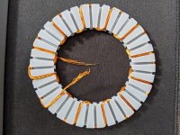
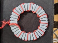
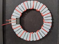
Okay, I have printed a few of these stators and wound them with various types of wire and take a look at the results.

A. Single strand of untwisted litz wire wound continuously. I was able to get 3 laps, and the 4th became difficult. I gave up, because the stator ended up breaking from pulling too tightly. It kept popping out of the slot on the 3rd and much more on the 4th lap. Pulling it tight only made that worse.
resized-image-Promo (47).jpeg


B. 6 Strands of litz wire. Each strand was untwisted and bundled together (still untwisted). The key here is to not twist the bundle together. When it was twisted it was too fat to fit in the slot. I could mush it in with a tool when it was untwisted. Once it was in the slot I could twist it (the slot cross section is a circle). Twisting the wire after allowed it to stay in place as I turned the corners, and allowed me to pull things pretty tight. This worked pretty well, and if it wasn't for my strands being too short, it probably would have been a really good test. The stator did break during winding, but I just kept going, and it sort of stitched itself together. This is still an option, but would require soldering each strand together at the beginning/end of each lap.
resized-image-Promo (46).jpeg

C. Single strand of twisted litz wound continuously. This has 5 laps (I didn't have enough wire in the spool for more). This worked great. its a very tight winding, which I think is important. It takes a bit to go around multiple laps, but it's much easier to manage. The first 3 laps are a breeze, then I mushed the wires down and kept going repeating that every lap, or as needed. By the 5th lap things were getting more difficult, and it makes me think 6 laps would be quite a struggle. I know I have flip flopped a bit, but I think this is the way to go. This would not require soldering at the beginning/end of each lap, and event the pictures show that it sticks out less on the inner and outer diameter. So thats a nice bonus. Also this stator did not break, and I was able top pull things very tight due to how the wire sits in the slot.
resized-image-Promo (48).jpeg


So there is it, twisted litz is back, and I think its here to stay. I still need to wind a stator with all 3 phases, which might present its own challenges, but we shall see. While it's not the 6 turns I was hoping for, its more than my Mk3 motor, and going from a 11mm to ~7 mm air gap.

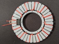
As far as mounting it goes.... I think I am going to try going with the out runner still. I really don't think I am going to be able to add printed supports to the stator. So I have designed a ring that sits in the middle of the stator that I am thinking I can epoxy in place. It might add some weight to do that, but the epoxy will stiffen things and be stronger than any printed solution. I realize that this will be thermally limited, and thermally resistant epoxies will be needed to further development beyond testing. But I think I can get away with it as a temporary solution. The outrunner design also allows me to re-use the rotor design I already have, which I have already printed a handful of, and would like to use.
resized-image-Promo (49).jpeg


I also bought some TRB-4458 thrust bearing washers. These are relatively close to the same dimensions as the magnets. I'm sure there will be some power loss due to the magnets extending over the edge of the back iron, but again, it should suffice for now. I realize this means that I need to redesign my rotor anyway, but I should be able to re-use a lot of the same geometry instead of starting over.

Moving right along.
 
HalbachHero said:
Thanks! I have to say. I have been completely distracted by this project lately. It's been a lot of fun to have others that can contribute ideas. I talk to my friends and my wife about this stuff, and its clear I'm a crazy person. I can't imagine this pace will continue forever, but It's been a lot of fun to see it take a bit of a turn to this simulation stuff. It's something I always wanted to do, but never spent the time to learn.
It is a really cool project but to much "niche" for sharing with a lot of people. You got me back on the simulation part I was trying to leave and instead do the real thing but it might not be a bad thing.

HalbachHero said:
I have pushed a few updates. I will work to include more information on the page, like a link back to the Git repo, and a version number. I would appreciate it if you could try using the tool again, and see it its working better with your inputs. I also will add support for those other variables that are not available in the form. Not sure why I didn't include those initially. For now you can manually edit the output at the bottom of the page.

As you mentioned, I tried to write this as best as I could with my understanding of the language. As you may notice, I did not use arrays virtually anywhere. I think there is room to clean things up further by doing this, but I felt it was significantly easier for me to avoid them for now. I can certainly see a more dynamic approach to making the objects. Also, I need to play around with coils because I am not sure yet how to build or evaluate data around them. But I do see the materials, and understand the concepts that it might take to implement. I'll see what I can do

I tried it again and for sure now the no hallback generation work flawlessly too so :bigthumb: .
I'll try to come up with the coil generation part when I find the time to do so. It will be a really good tool for optimising axial designs so it's worth doing. I've still got to read through all your code to understand it completly so it might not be soon. I've read arrays or a bit odd to work with in LUA so if you made it work without them it's not a bad thing.

HalbachHero said:
So there is it, twisted litz is back, and I think its here to stay. I still need to wind a stator with all 3 phases, which might present its own challenges, but we shall see. While it's not the 6 turns I was hoping for, its more than my Mk3 motor, and going from a 11mm to ~7 mm air gap.

It sure look more tight with the wire twisted. The end turn is clearly what's making hard for untwisted ones. Going frow 11 to 7 mm even with a turn less will go a long way to reduce KV so all good there !
 
Okay. I found a few more bugs with the simulation generator, issue with airgap and analysis line placement. I think I have resolved them for the most part. There is still one known issue which appears if the halbachs and regular magnets are different sizes.
https://cjohnson25.github.io/femm-sim-gen-app/

I used this to calculate the difference between the previous design potentially what the new one could be. It looks like the flux will increase by 2.3 times, and there are 25% more turns. So if I was at a 212Kv before would it be reasonable to assume I could do down to about ~75?

If so, that would be super cool. Assuming it can handle the same current @32A maybe more with more testing, that could be a 1.7Kw motor @~53V (~4000RPM, that's the fastest I have felt safe spinning them), and would weigh roughly 400g. All total guess work at the moment, but wouldn't that be something.
 
Great thread :) Not caught up yet, I'd posted a 3d printable layout in APL's thread intended to minimise end turn bulk. No idea if it's any good as I still haven't got as far as testing it:
https://endless-sphere.com/forums/viewtopic.php?f=30&t=97860&start=1275#p1594720
https://endless-sphere.com/forums/viewtopic.php?f=30&t=97860&start=1275#p1595361
 
stan.distortion said:
Great thread :) Not caught up yet, I'd posted a 3d printable layout in APL's thread intended to minimise end turn bulk. No idea if it's any good as I still haven't got as far as testing it:
https://endless-sphere.com/forums/viewtopic.php?f=30&t=97860&start=1275#p1594720
https://endless-sphere.com/forums/viewtopic.php?f=30&t=97860&start=1275#p1595361

Yes! I recall seeing this when reading APLs thread. This is a clever design, and I really like that it has the potential to add magnets to the outer diameter of all of that to get even more over the ends. like having 3 rotors in a single motor. 3D printing may certainly make that geometry a possibility. Would be happy to try to print that cage piece if you were inclined to share the model. My concerns would be fragility in the cage and the amount of soldering involved in connecting all the turns (from experiences with my own designs), but I see the potential.
 
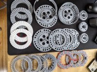
Also, just wanted to share. The printer has been busy lately. Lots of old stator designs I'm probably going to keep for posterity. Lots were printed that now in the heap of other failed prints, but its kinda neat to see it all. Though its really taking over my desk now

resized-image-Promo (50).jpeg
 
stan.distortion said:
Great thread :) Not caught up yet, I'd posted a 3d printable layout in APL's thread intended to minimise end turn bulk. No idea if it's any good as I still haven't got as far as testing it:
https://endless-sphere.com/forums/viewtopic.php?f=30&t=97860&start=1275#p1594720
https://endless-sphere.com/forums/viewtopic.php?f=30&t=97860&start=1275#p1595361

I like the idea ! There are just two things I need to get my head around :
- How do you do more than 1 Turn per stator Pole
- How to keap a tight airgap when the stator is going to be tappered (maybe a same tapered rotor ? )
Looking forward to see one tested :)

HalbachHero said:
I used this to calculate the difference between the previous design potentially what the new one could be. It looks like the flux will increase by 2.3 times, and there are 25% more turns. So if I was at a 212Kv before would it be reasonable to assume I could do down to about ~75?

If so, that would be super cool. Assuming it can handle the same current @32A maybe more with more testing, that could be a 1.7Kw motor @~53V (~4000RPM, that's the fastest I have felt safe spinning them), and would weigh roughly 400g. All total guess work at the moment, but wouldn't that be something.

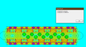
Being excited with the figure you gave (those approximations should be close) . I actually did a simulation using the dimensions you provided before adding two stator poles in it and here are the results :
The setup :
sim_setup.PNG
Total force on coils results :
coil_hall_sim.PNG

Here the current are 0A in phase1 27.71 in phase2 and -27.71 in phase3 correponding to Ipeak = 32A. With phase 1 being center on magnet pole, max torque is achieve with 0 electrical degree on this phase (the other two are 120 and 240 behind).
As for the resut we get 6.52 N for two stator pole. It is for a 12.7mm deep simulation (magnet lenght)
So with 12 total stator poles on your design it lead to F=39.1275N.
I extrapolate from your previous picture that mean rotor radius is 38.8mm so Torque=39.1275*0.0388= 1.518 N/m
so Kt(rms)=1.518/22.62=0.0671 N/Arms => Ke(rms)= 0.0671/root(3) = 0.03874 Vrms/rad.s => Ke(peak)= 0.03874*root(2) = 0.05479 V(peak)/rad.s => Kv = (1/Ke(peak))*(60/2pi) = 174.27 RPM/V

I might have messed up something somewhere but that's what I end up with ... :?
I might need to try other currents value to make sure I eyeballed the stator flux placement correctly .
 
HalbachHero said:
...]
Yes! I recall seeing this when reading APLs thread. This is a clever design, and I really like that it has the potential to add magnets to the outer diameter of all of that to get even more over the ends. like having 3 rotors in a single motor. 3D printing may certainly make that geometry a possibility. Would be happy to try to print that cage piece if you were inclined to share the model. My concerns would be fragility in the cage and the amount of soldering involved in connecting all the turns (from experiences with my own designs), but I see the potential.

Uploaded them to thingverse but they're probably not much use, the outer covers and bearing carriers aren't drawn yet and it could be a lot simpler (I was trying to get a good cooling airflow path with that one).
https://www.thingiverse.com/thing:4844437

The outer covers are responsible for alignment, slotted to match the inner frame and it needs support between the windings and rotor faces, a 2 or 3 layer thick skin should be plenty. The rotor needs a steel disk between the magnets and the poles orientated back to back, so long as the rotor runs true it should be possible to get very close tolerances by tweaking the thickness of the support ring that goes around the rotor circumference.

Thecoco974 said:
...
I like the idea ! There are just two things I need to get my head around :
- How do you do more than 1 Turn per stator Pole
- How to keap a tight airgap when the stator is going to be tappered (maybe a same tapered rotor ? )
Looking forward to see one tested :)
...

The windings can be done in a simple loop beforehand and slotted into place on assembly, cages built up around the rotor first, then windings pushed into place, then outer covers and shielding fitted over the windings. It would be more awkward with multiple rotors as it would have to be built up one rotor at a time and the windings threaded through the covers but still a lot simpler than winding a ring. The rotor is flat, the taper is just on the outside and comes from keeping the same cross sectional area as the windings get narrower towards the centre.

Magnets are only 20x10x2mm and it might look like a hell of copper for just 12 little magnets but I'd spent a lot of time working it out in FEEM and that seems to be what's needed to get good performance out of coreless, an awful lot more copper/magnet than cored motors.

Tbh, that's why I didn't go any further with it. The aim was saving weight and it didn't work out that way, any saving was lost to the extra copper. Aluminium windings seem to be the only option for making significant weight savings but several folk here have warned they're a total minefield, nothing like as simple as they seem.
 
Thecoco974 said:
Being excited with the figure you gave (those approximations should be close) . I actually did a simulation using the dimensions you provided before adding two stator poles in it and here are the results :
The setup :

Total force on coils results :
View attachment 1

Here the current are 0A in phase1 27.71 in phase2 and -27.71 in phase3 correponding to Ipeak = 32A. With phase 1 being center on magnet pole, max torque is achieve with 0 electrical degree on this phase (the other two are 120 and 240 behind).
As for the resut we get 6.52 N for two stator pole. It is for a 12.7mm deep simulation (magnet lenght)
So with 12 total stator poles on your design it lead to F=39.1275N.
I extrapolate from your previous picture that mean rotor radius is 38.8mm so Torque=39.1275*0.0388= 1.518 N/m
so Kt(rms)=1.518/22.62=0.0671 N/Arms => Ke(rms)= 0.0671/root(3) = 0.03874 Vrms/rad.s => Ke(peak)= 0.03874*root(2) = 0.05479 V(peak)/rad.s => Kv = (1/Ke(peak))*(60/2pi) = 174.27 RPM/V

I might have messed up something somewhere but that's what I end up with ... :?
I might need to try other currents value to make sure I eyeballed the stator flux placement correctly .

I measured the magnet slots in my design, and got an average radius, of 39.55 not a dramatic difference. Also, I'm not sure how this works exactly, but I think there are 24 poles per phase, due to the legs being on each side and aligning with opposite magnetic fields at the same time.

Given the change in poles, and the fix to rotor diameter. I get a Kv of 85.5. More in line with my theory, but I really don't know all the math involved in calculating those values, so I cannot say if those are correct or not.

One way to find out, is to build one :D


stan.distortion said:
Uploaded them to thingverse but they're probably not much use, the outer covers and bearing carriers aren't drawn yet and it could be a lot simpler (I was trying to get a good cooling airflow path with that one).
https://www.thingiverse.com/thing:4844437

...

Tbh, that's why I didn't go any further with it. The aim was saving weight and it didn't work out that way, any saving was lost to the extra copper. Aluminium windings seem to be the only option for making significant weight savings but several folk here have warned they're a total minefield, nothing like as simple as they seem.

Thanks I downloaded them I understand what you're saying with the bearing carriers. If you design it out more, let me know! It's certainly a novel axial flux design.

I am similarly going for a high power to weight ratio, so I appreciate the insight. I have not considered aluminum windings, but at this point the rotors are the heaviest part of my design, and given my findings, I need to add iron to everything anyway which will only add more weight, but I do wonder if there is some magnet trickery that can lead to higher flux density passing over the coils, and if tolerances can be close enough, that adding iron to the core would only result in more losses than gains. But I really don't know. I have no math to prove it. It's simply a thought.
 
stan.distortion said:
The windings can be done in a simple loop beforehand and slotted into place on assembly, cages built up around the rotor first, then windings pushed into place, then outer covers and shielding fitted over the windings. It would be more awkward with multiple rotors as it would have to be built up one rotor at a time and the windings threaded through the covers but still a lot simpler than winding a ring. The rotor is flat, the taper is just on the outside and comes from keeping the same cross sectional area as the windings get narrower towards the centre.
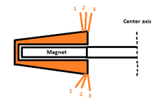
I'm might be slow but I want to make sur I have really understood your design idea so I made a crude sectional view of what I think it look like :
cut_view.PNG

If i'm correct for multiple turns you need some isolated strand in the coil and then connect each one individually between each coil of the same phase.
Also If I understand it corectly magnetic flux path is open behind the copper making it really weak (would explain why you need a lot of magnet and copper mass to make some power). Or is it the shielding on top of the coil that's coing to redirect magnetic flux ? In that case it need to be laminated or ferrite/smc to cut on eddy current.
If doing multiple rotor it would mean one is facing the flat side of the coil and the other the tapered side ?

HalbachHero said:
I measured the magnet slots in my design, and got an average radius, of 39.55 not a dramatic difference. Also, I'm not sure how this works exactly, but I think there are 24 poles per phase, due to the legs being on each side and aligning with opposite magnetic fields at the same time.

Given the change in poles, and the fix to rotor diameter. I get a Kv of 85.5. More in line with my theory, but I really don't know all the math involved in calculating those values, so I cannot say if those are correct or not.

One way to find out, is to build one

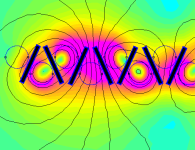
In my simulation there is 2 stator pole of each phase, what I call a stator pole is one strand going out + one strand going toward the center, having an opposed current flowing flowing trough them they create an axially oriented mlagnetic field interacting with rotor magnetic field to create torque. I ran the simulation with the coils only :

coil_field.PNG

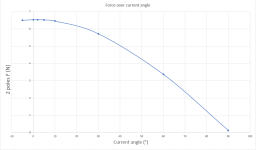
As you can see by varying the current on the 3 different coils pairs (following a three phase current waveform) we get two rotor magnetic poles. Varying current angle will produce more or less torque in regards to rotor placement. For making sure I had it correctly aligned for max torque I re-ran a few simulations varying current phase angle and here is the force graph over phase I got :

Force over current vector placement.PNG

So my eyebaling was actually spot one the max torque phase angle.

How did you mesure the previous motor Kv value ? (those constants are not really clear on whether they use Peak phase voltage or rms phase voltage, it should be peak value as I foud out a few days ago).

If we could match the simulation result with your findings it will be great for future version optimisation :D .
 
Thecoco974 said:
...
If i'm correct for multiple turns you need some isolated strand in the coil and then connect each one individually between each coil of the same phase.

Yes, each of those segments are one side of loop of windings with the other side of the loop 3 segments away. There are 18 segments in that drawing, that works out at 3 windings per phase and could be connected in series or parallel and the phases star or delta. The end turns aren't drawn but work out fairly tidily, there's no way of avoiding them taking up space but with that layout they're only adding a little to the diameter. They add to the width but that could work well with multiple rotors as there aren't any end turns needed between rotors, only at the outer faces.

Also If I understand it corectly magnetic flux path is open behind the copper making it really weak (would explain why you need a lot of magnet and copper mass to make some power). Or is it the shielding on top of the coil that's coing to redirect magnetic flux ? In that case it need to be laminated or ferrite/smc to cut on eddy current.

It does, iirc they add about 40% to the torque in FEEM. Easy enough to cut, just a round ring with a slight dish. I was going to do them out of shim steel as I have it on hand an it can be cut with a good pair of scissors. It's the grey disk in this screenshot and should probably extend all the way over the circumference to be correct but the disk is simple and would be enough to test.


If doing multiple rotor it would mean one is facing the flat side of the coil and the other the tapered side ?
It's the obvious next step but massively complicates it. The front and back faces of the windings could be made parallel and that could be a step forward as it allows the windings to be spaced in different ways, good for fine tuning a waveform (btw, the rectangular magnets where just some I had to hand at the time and would probably work ok for an RC ESC but disk magnets would likely be better for a sine wave controller). Maybe external rotors would be a good step if parallel winding faces worked out, idk.

I'm very much a noob with motor design and wouldn't be one bit surprised if there's some major noobish mistake in that layout, not much easily digestable info on coreless out there. Sorry if it's distracting from the thread btw, it's been progressing impressively quickly!
 
stan.distortion said:
Sorry if it's distracting from the thread btw, it's been progressing impressively quickly!

No worries. I appreciate the input and creative ideas. That's how progress is made. I would love to see the progression of your motor if you decide to pursue it. Also happy to print it and give it a go if you nail down the design. Perhaps Ill take a swing at modifying it to work with my magnets.


Thecoco974 said:
How did you mesure the previous motor Kv value ?

Well... not in the best way. In fact thinking about it now, its probably an entirely invalid value to go by. I had a 20" propeller on it with a 4S LiPo battery and a hobby ESC (The setup I have in the Mk3 Video). The Kv calculation I did was purely based off the readout on the power meter, and a tachometer. So It's likely inaccurate, for a number of reasons.

Thank you for running those sims. Looking at your screenshots, it appears that the magnets do not align directly with a single phase, but as you said, you re-ran a few sims and adjusted that angle, so I'm assuming you caught that already and I trust your math over mine :)

I will see If I can get it running nicely again. Perhaps I could run a better test, or we can run a simulation for the old rotor too to compare the two. I would like to add coil support in the program I made. I will try to do that in the coming days. Still trying to finish up the bathroom project too (week 3, oof)

I made some progress with winding the stator too. Basically each phase is harder than the last, the third lap on phase 3 was tough, still two more to go, but its getting there, and it hasn't broken (knock on wood)

Also still thinking of the best way to make the rotors. given the washers I purchased. I want to keep things as thin as possible, but I think I will need to add print a carrier for the magnet/back iron assembly. This way I can still have my support ring and heat-set inserts as I have previously.

I have thought about having the back iron just be a larger diameter than the magnets to allow a mounting point. directly on the back Iron to keep it slim, but I wonder if that would cause issues the magnetic field.
 
More winding turns will definitely help.

Here's another crazy idea:

If you put little strips of iron lamination in the spaces between windings, it will greatly increase the torque/amp. While the iron adds weight, the increased torque will offset it and you may get a better overall power/weight ratio. The iron could just be pieces harvested from an old-school iron transformer core. The iron weight would be a small fraction of a typical iron stator.

Of course there will be some challenges keeping them in place and winding around them. Ideally you'd want little wedge shaped iron pieces but hard to make. Flat ones would be easy.

Core motor windings.jpeg

I got this idea from the Etek motor design. Worked wonders for those.
You can see how that looks here:
https://en.wikipedia.org/wiki/Lynch_motor
 
fechter said:
More winding turns will definitely help.

Here's another crazy idea:

If you put little strips of iron lamination in the spaces between windings, it will greatly increase the torque/amp. While the iron adds weight, the increased torque will offset it and you may get a better overall power/weight ratio. The iron could just be pieces harvested from an old-school iron transformer core. The iron weight would be a small fraction of a typical iron stator.

Of course there will be some challenges keeping them in place and winding around them. Ideally you'd want little wedge shaped iron pieces but hard to make. Flat ones would be easy.

As far as fitting more windings. I either needs to sacrifice some of the strands in the litz wire to fit more loops in the same thickness, otherwise, I need to go thicker, which could mean larger magnets. Would a larger diameter help, or would that only improve torque?

The little metal bits I think are a great Idea. I was wondering the other day if that might help or hinder. Any thoughts on optimization there? Since the wire channels are staggered, there's room on the back of each of the guides, that I could design in a slot for a piece of metal to fit. Essentially every leg would look like a lollipop. I really want to run some sims with this.

I realize that it would no longer be an air core, but it still seems like its still possible to print and assemble cheaply/easily, and if a little extra weight adds a lot of extra power, I'm in.
 
On the Lynch motor, I think they used some kind of ferrite, like the SMC stuff. I was thinking more like lamination strips harvested from an old transformer core. It would be interesting to see how it models. If the iron pieces are too thin, I think they would be prone to saturating, but this is a somewhat unusual configuration. The Lynch motor has outstanding power/weight.

Optimizing may take some trial and error. The iron pieces should be the same width as the magnets and the more you can stuff in, the better, I would think. If angling them to fit around the copper helps, I don't think it would add much loss. It would be interesting to see how various thicknesses of iron affects the model. I could imaging sort of a zig-zag pattern for the iron. Like this, only the ends should be beveled so they are parallel to the rotor face.

slanted iron.png

The magnets are going to put a lot of force on them and they will want to slide out of the slots and bend the stator. Some kind of key or hole in the iron to lock them in place will be needed. Potting the entire core in epoxy might work, but epoxy gets soft when it gets hot. If there was any space left to blow air through the windings, it would help with cooling. Since the outer part of the winding will be exposed, a lot of heat can be extracted from that section.

I don't remember ever seeing a brushless motor built like this.
 
fechter said:
On the Lynch motor, I think they used some kind of ferrite, like the SMC stuff. I was thinking more like lamination strips harvested from an old transformer core. It would be interesting to see how it models. If the iron pieces are too thin, I think they would be prone to saturating, but this is a somewhat unusual configuration. The Lynch motor has outstanding power/weight.

Optimizing may take some trial and error. The iron pieces should be the same width as the magnets and the more you can stuff in, the better, I would think. If angling them to fit around the copper helps, I don't think it would add much loss. It would be interesting to see how various thicknesses of iron affects the model. I could imaging sort of a zig-zag pattern for the iron. Like this, only the ends should be beveled so they are parallel to the rotor face.


The magnets are going to put a lot of force on them and they will want to slide out of the slots and bend the stator. Some kind of key or hole in the iron to lock them in place will be needed. Potting the entire core in epoxy might work, but epoxy gets soft when it gets hot. If there was any space left to blow air through the windings, it would help with cooling. Since the outer part of the winding will be exposed, a lot of heat can be extracted from that section.

I don't remember ever seeing a brushless motor built like this.


I think it's a really clever idea, but makes me think manufacturing that could be very difficult. Also given the potential for saturation, is it possible that having a 3d printed ferrous core would be a more suitable? Or would the ferrous material have to be isolated from each other somehow?

If the ferrous material needs to be the width of the magnet, might there be benefit in having thinner magnets to fit more poles?
 
stan.distortion said:
It does, iirc they add about 40% to the torque in FEEM. Easy enough to cut, just a round ring with a slight dish. I was going to do them out of shim steel as I have it on hand an it can be cut with a good pair of scissors. It's the grey disk in this screenshot and should probably extend all the way over the circumference to be correct but the disk is simple and would be enough to test.
I've seen it a used as a magnetic yoke, it's good for increasing torque for sure ! Were do you get steel shiming in large roll like that ?

stan.distortion said:
btw, the rectangular magnets where just some I had to hand at the time and would probably work ok for an RC ESC but disk magnets would likely be better for a sine wave controller
Not sure why that is .. I actually did see this statement on Lebowsy motor build thread but for me there is no such thing in aircored motor. I can see why in cored motor flux switch more or less abrutly from one magnetic circuit to the next creating a squarish BEMF, but with aircored like we are studying magnetic BEMF should follow the magnetic flux density waveforme that is kind of sinusoidal. I might miss something here though ...

HalbachHero said:
Well... not in the best way. In fact thinking about it now, its probably an entirely invalid value to go by. I had a 20" propeller on it with a 4S LiPo battery and a hobby ESC (The setup I have in the Mk3 Video). The Kv calculation I did was purely based off the readout on the power meter, and a tachometer. So It's likely inaccurate, for a number of reasons.

The best way would be to probe the line to line voltage with an oscilloscope, spinning it with a drill and doing the calculation from peak voltage. If like me you don't have an oscilloscope (yet) you can hook up a simple full wave bridge rectifier and monitor output voltage with a multimeter. the average output of a three phase bridge rectifier is 0.953*V(peak) so you can get a good value that way too.

HalbachHero said:
I have thought about having the back iron just be a larger diameter than the magnets to allow a mounting point. directly on the back Iron to keep it slim, but I wonder if that would cause issues the magnetic field.

No you can do it, magnetic flux will always choose the least resistive path so only the space between to magnet. That might allow for a smaller diameter rotor with rigid mounting.


HalbachHero said:
I think it's a really clever idea, but makes me think manufacturing that could be very difficult. Also given the potential for saturation, is it possible that having a 3d printed ferrous core would be a more suitable? Or would the ferrous material have to be isolated from each other somehow?

If the goal is only to improve the Torque/amp rating going with iron core is proably a better way. We loose all the advantages of coreless (no iron losses/cogging torque) that permit high RPM and high power with low losses.
I actually thought of a way to had iron to the mix but it will be a pain to do it that way.

fechter said:
but epoxy gets soft when it gets hot
Going full epoxy is actually what I though of :lol: . There is actually some epoxy with higher GT temps that are I think sufficient for our use (I've seen some with 115° Glass transition temperatures after heat curing and plan on using one of those).

My idea was to print a coil carrier out of PVA filament, wind it, impregnate it with epoxy (and some heat conductive additive if we are there) then dissolve the carrier in water and finally cast it in iron powder and HT epoxy. Quite a process ! but might be worth it in your case :

ironcore_in_the_air.PNG

Look at those clean flux lines :lol: I just made an iron block around it so not feasible in practice but the results speak for them self :

22.74 N for 2 stator pole, so 5.396 Nm and a Kv of only 49 (3.55 time less than before if i'm correct)

also with the magnectic reluctance so low now every piece of metal is near saturation.
More realisticly I can make a simulation with achievable iron content (something like 70% maybe) and using real value of those mix someone calculated on youtube (https://www.youtube.com/watch?v=YQNW4ZTsg2w)
 
fechter said:
On the Lynch motor, I think they used some kind of ferrite, like the SMC stuff. I was thinking more like lamination strips harvested from an old transformer core. It would be interesting to see how it models. If the iron pieces are too thin, I think they would be prone to saturating, but this is a somewhat unusual configuration. The Lynch motor has outstanding power/weight.

Optimizing may take some trial and error. The iron pieces should be the same width as the magnets and the more you can stuff in, the better, I would think. If angling them to fit around the copper helps, I don't think it would add much loss. It would be interesting to see how various thicknesses of iron affects the model. I could imaging sort of a zig-zag pattern for the iron. Like this, only the ends should be beveled so they are parallel to the rotor face.

The magnets are going to put a lot of force on them and they will want to slide out of the slots and bend the stator. Some kind of key or hole in the iron to lock them in place will be needed. Potting the entire core in epoxy might work, but epoxy gets soft when it gets hot. If there was any space left to blow air through the windings, it would help with cooling. Since the outer part of the winding will be exposed, a lot of heat can be extracted from that section.

I don't remember ever seeing a brushless motor built like this.

Very interested in trying this. I am curious how it will affect the structural integrity of the stator, whether it will improve it or make it worse. I will definitely try something like this in the future. Another though I had was to line the inner wall of the wire guide channel with a ferrous material, in a semi circle or "U" shape.

Eventually we will get there. I need to iterate my way there, or ill be stuck in what-if land.


Thecoco974 said:
The best way would be to probe the line to line voltage with an oscilloscope, spinning it with a drill and doing the calculation from peak voltage. If like me you don't have an oscilloscope (yet) you can hook up a simple full wave bridge rectifier and monitor output voltage with a multimeter. the average output of a three phase bridge rectifier is 0.953*V(peak) so you can get a good value that way too.

Yeah I do not have an oscilliscope, and would not even really know how to use one if I did, but I can learn, and I would love to visualize the wave form. Are there any reasonably priced 3 channel ones? I also know nothing about brand reputation for those devices. Would love some recommendations.

Thecoco974 said:
No you can do it, magnetic flux will always choose the least resistive path so only the space between to magnet. That might allow for a smaller diameter rotor with rigid mounting.

Yeah, currently thew plastic bends from the magnets pulling to one another. Having a solid backing would be great, but I think I would need to fabricate those. I have not been able to find a standard thrust bearing washer that I can purchase with the correct dimensions, and unfortunately I don't have the best tools for working with metal.

Thecoco974 said:
If the goal is only to improve the Torque/amp rating going with iron core is proably a better way. We loose all the advantages of coreless (no iron losses/cogging torque) that permit high RPM and high power with low losses.
I actually thought of a way to had iron to the mix but it will be a pain to do it that way.
If I was to go with an iron core I would hope that I could get away with a minimal amount of iron (likely will be saturated) to improve torque without adding too many losses. There must be a balance, but what I don't know either is how saturated iron would affect those losses.

Thecoco974 said:
Going full epoxy is actually what I though of :lol: . There is actually some epoxy with higher GT temps that are I think sufficient for our use (I've seen some with 115° Glass transition temperatures after heat curing and plan on using one of those).

My idea was to print a coil carrier out of PVA filament, wind it, impregnate it with epoxy (and some heat conductive additive if we are there) then dissolve the carrier in water and finally cast it in iron powder and HT epoxy. Quite a process ! but might be worth it in your case :
I was considering and high temp epoxy for the mounting all of this, but I like the idea of making the PVA carrier. I didn't even know about that material. I wonder if this idea could be combined with APL's homemade SMC material??

Thecoco974 said:
Look at those clean flux lines :lol: I just made an iron block around it so not feasible in practice but the results speak for them self :

22.74 N for 2 stator pole, so 5.396 Nm and a Kv of only 49 (3.55 time less than before if i'm correct)

also with the magnectic reluctance so low now every piece of metal is near saturation.
More realisticly I can make a simulation with achievable iron content (something like 70% maybe) and using real value of those mix someone calculated on youtube (https://www.youtube.com/watch?v=YQNW4ZTsg2w)
It's beautiful. I realize that's not realistic, but if you thinned out the iron, and kept the wires in place, that's pretty close to a cross section of what mine looks like. I don't want to incorporate a lot of iron losses but, those numbers sure are fascinating...
 
I'm moderately against the iron.

I've been quietly following this, resisting the temptation to add another project to my list but...

1) iron makes this much less diy able. As it stands now, i could print this at home, wind it, poke some magnets in and be basically done
2) APLs thread seems to have become a quest for ever more stiffness. It's not in any way a cheap diyable motor.
3) with no iron losses, you can just spin faster surely to gain power?
4) get lower kV by making an extra slice of rotor and stator? I think there are probably gains to be had like fewer magnets in the extra slices, no need for iron etc and the distances are larger than rotor to stator so less stiffness needed.

Just my 2c.
 
Back
Top