Dogati Electric Superleggera

Can we have some pictures of the bike please?


It looks very interesting.


But....why is the seat so far forward in the real bike and in the CAD model prototype?
 
j3tch1u said:
Miles said:
I like it, Ben (apart from the forks...) :D

I'm not happy with them either.
...

Hydraulically damped telescopic forks have been pretty popular since the 1930s, is there a particular reason you're pursuing alternative designs?

I'm interested to understand the seat too, I can't quite figure out the positioning either.

The Voltra design concept also uses went for a exposed red trellis frame:
http://www.coroflot.com/public/individual_file.asp?individual_id=228481&portfolio_id=3032334&
 
Mark_A_W said:
Can we have some pictures of the bike please?


It looks very interesting.


But....why is the seat so far forward in the real bike and in the CAD model prototype?


mark, pics of my bike are on page 1. the baby bimota has yet to be built (still waiting for my welder and tube bender). the seat is on a parallel link 3-point seatpost. forward for dh/trials type riding, upright for pedalling and rear-ward for high speed tucks. all adjustable from a remote lever. works really well.
 
voicecoils said:
j3tch1u said:
Miles said:
I like it, Ben (apart from the forks...) :D

I'm not happy with them either.
...

Hydraulically damped telescopic forks have been pretty popular since the 1930s, is there a particular reason you're pursuing alternative designs?

I'm interested to understand the seat too, I can't quite figure out the positioning either.

The Voltra design concept also uses went for a exposed red trellis frame:
http://www.coroflot.com/public/individual_file.asp?individual_id=228481&portfolio_id=3032334&


well..they are more rigid than telescoping forks and i can play with different shocks/spring/dampening rates. i think linkage forks can look rad and function well if they are done right.
will also be doing something "special" with the fork legs ;)

the voltra is really nice. i read the interview with dan anderson. i wish i had that kind of talent :D
 
j3tch1u said:
Mark_A_W said:
Can we have some pictures of the bike please?


It looks very interesting.


But....why is the seat so far forward in the real bike and in the CAD model prototype?


mark, pics of my bike are on page 1. the baby bimota has yet to be built (still waiting for my welder and tube bender). the seat is on a parallel link 3-point seatpost. forward for dh/trials type riding, upright for pedalling and rear-ward for high speed tucks. all adjustable from a remote lever. works really well.


Please, there is only one picture of the bike, and it's very hard to make out details.


Can we have some MORE PICS PLEASE??
 
Mark_A_W said:
Please, there is only one picture of the bike, and it's very hard to make out details.


Can we have some MORE PICS PLEASE??


mark, there are very clear pictures and details of the parts i had a hand in making which is what i wanted this build thread to be about. there will be pics of a complete bike in logical procession as it is fleshed out. however i won't be posting any more shots of that test mule--it' has already been torn down for blueprinting. you will have to be patient. also, please refrain from using large caps on my build thread--i can hear you just fine :)
 
Nice concept bike! Just a suggestion for your bender, mount it as they suggest. Don't get fancy like I did and try to mount it on the vertical for space reasons, it makes it very hard to actually use.

Can't wait to see what you come up with!
 
johnrobholmes said:
Nice concept bike! Just a suggestion for your bender, mount it as they suggest. Don't get fancy like I did and try to mount it on the vertical for space reasons, it makes it very hard to actually use.

Can't wait to see what you come up with!

thanks for the tip jrh--i was thinking of maybe just bolting it to a work-table with a stand-off--didn't get the stand cuz it would've cost more to ship (already $250 to taiwan). make anything new lately?
 
Just made some more handlebars, getting my marking and precision down. I am redoing the front end of my pit bike today too. Not sure if I will need any bends for that frame.

I have drawn up a few bikes. I am almost set on doing a hybrid for my next vehicle. I just can't stand spending $800 on a pack that may only get me 20 miles when I can get a gas setup for a few hundred that will get me 100 miles to the gallon. So maybe I compromise and get a $400 battery pack and have best of both worlds, minus the extra weight?
 
Hello all,

First (though it's a long thread I've said this before probably) very cool work and ideas...

I read in the thread that the electromagnetic clutch wasn't cutting the mustard for you and just wouldn't hold under the torque of the drive/power...

In seeing the exploded model of that first incarnation (or maybe the second model) - the idea occoured to me - why not a hydrolic (use a brake MC) or pnuematic (don't ask me where from) - or even screw type friction clutch... I would think considering how mechanical disc brake calipers work by rotating their way out... you could perform a similar automated mechanism to engage a modified non metallic disc brake pad (or somthing similar) to a replaceable stainless steel faceplate.

This would cause the clutch to lock up... really it could be simplest if you simply daisy chain off existing brake cable pulls (if possible) with a ysplit and adjust so when you pull the brakes a little bit to engages the clutch... the more you engage, the more the clutch locks (actually it will lock pretty quick) which will enable your regen only when you pull the levers.

Someone may have already hit on this - the matex coupling as a stator was darn cool I must admit!

Can't wait to see it done!

-Mike
 
mwkeefer said:
Hello all,

First (though it's a long thread I've said this before probably) very cool work and ideas...

I read in the thread that the electromagnetic clutch wasn't cutting the mustard for you and just wouldn't hold under the torque of the drive/power...

In seeing the exploded model of that first incarnation (or maybe the second model) - the idea occoured to me - why not a hydrolic (use a brake MC) or pnuematic (don't ask me where from) - or even screw type friction clutch... I would think considering how mechanical disc brake calipers work by rotating their way out... you could perform a similar automated mechanism to engage a modified non metallic disc brake pad (or somthing similar) to a replaceable stainless steel faceplate.

This would cause the clutch to lock up... really it could be simplest if you simply daisy chain off existing brake cable pulls (if possible) with a ysplit and adjust so when you pull the brakes a little bit to engages the clutch... the more you engage, the more the clutch locks (actually it will lock pretty quick) which will enable your regen only when you pull the levers.

Someone may have already hit on this - the matex coupling as a stator was darn cool I must admit!

Can't wait to see it done!

-Mike


thank you mike--better late than never :D

good ideas. i see your reasoning behind the mechanical approach but i can't think of an easy way to implement this. rotor and clutch hub need to rotate with respect to each other so neither of those assemblies can have cables or hydraulic lines. the idea was to control it electronically so the mcu could engage on throttle/braking, disengage pedalling/coasting. holding down the lever during acceleration would be a little counter-intuitive and could get a little tiring. however, thank you for the suggestion!

i have a multiple wet plate clutch but it has too much friction in the disengaged state in addition to being heavy. the holding power under reverse geared braking force is also inadequate. so i've concluded a dog-type mag clutch would be ideal, but the mcu would have to spin the motor up to engagement speed. still haven't found a suitable mag dog clutch so the motor braking is on hold until after i build my new frame to properly house the mish-mash of components. however, i've reserved a space in the drive compartment for a future clutch :)

it's all coming together slowly--a lot of parts and tools in transit right now and still looking for a new shop space. i've got 5 dogs that co-habitate in my home-shop. don't want to blind them with the TIG (and they don't make auto-darkening welding helmets for pooches lol).
 
johnrobholmes said:
Just made some more handlebars, getting my marking and precision down. I am redoing the front end of my pit bike today too. Not sure if I will need any bends for that frame.

I have drawn up a few bikes. I am almost set on doing a hybrid for my next vehicle. I just can't stand spending $800 on a pack that may only get me 20 miles when I can get a gas setup for a few hundred that will get me 100 miles to the gallon. So maybe I compromise and get a $400 battery pack and have best of both worlds, minus the extra weight?

..or maybe a smaller pack and hi-power onboard charger so you can leech off the grid?
 
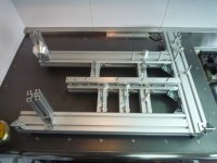
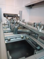
Finished making my jig for welding the Baby Bimota frame. I used a series of 30-60 and 30-30 aluminum extrusions and tried to leave the weld joints as accessible as possible. The jig can stand upright or be flipped for various welding positions. Stop-guides and locating pins can be moved around for future geometry changes to the frame. Two machined aluminum cones secure the head-tube and can be adjusted independently of each other.

P1140497.JPG

Close-up showing mish-mash of fasteners. Grub screws are used instead of shims for setting height offsets. They are adjusted to within .01mm tolerance. L-brackets serve as both guides and spring locks for the top and down tubes. The square cubes are stop-guides for the angled truss members. The aluminum cylinder to the right acts like a dowel pin to secure the frame bosses. The bar at the top locks all the trusses down in one shot. Everything is fixed with wing-nuts (no tools necessary) and all fasteners stay in place for repeatability. Mounting and tear-down can be done with gloves on and only takes a couple minutes.

P1140500.JPG
 
I've always admired the trellis frame and its functional beauty. This is a miniature version of that tried and true design.

The frame is welded in two-halves (one the mirror of the other). This jig does double-duty for both sides negating the need for two jigs (note the clearance near the head tube for the mirror half).

Gas holes were drilled in all the joints. If you look closely, there are gas holes in the head-tube cones as well--this is where the hot expanding gases ultimately evacuate from (which prevents it from escaping from the weld seams and causing turbulence).

The top/down tubes are 7/8" 1.2mm high-grade, Reynolds chromoly. The trusses are 18mm x 0.9mm. Mounting bosses are mild-steel countersunk M8. You can see from the picture, my notches were a little "loose". Using bi-metal hole saws on my lathe/tube notcher rips the thin-wall tubing to shreds in short order. I ordered some diamond grit hole saws but they are still due to arrive. Not wanted to wait, I used notching templates and a dremel instead. The online notching apps are pretty good in that they show you where to cut the inner and outer diameters. However, I thought I'd save time and use my Solidworks model to make the templates (unfolded using the sheet-metal feature). End result, I lost the inner guide-lines and ultimately wasted a lot of time hand fitting the joints with far less accuracy.

This was my first time TIG welding (as you can see from the sub-optimal quality) and i'm still on the steep end of the learning curve. Not the easiest 1st project to tackle (just jumped right in and didn't even bother practicing on scrap). Cannot stress enough the importance of tight fitting joints for the basis of good welds. Thin-wall tubing will melt in the blink of an eye and then [filler] Rod and Angle [grinder] become your best friends :oops: . Still a ways to go before I make the "stack of dimes" while "walking the cup" like the pros (they make it look so easy).

View attachment 2
P1140501.JPG
P1140513.JPG
 
johnrobholmes said:
Nice jig setup! Nice setup in general, looks like you are ready to crank em out.

Thanks JRH. That's the thing, I set everything up for production then chicken-out when it comes time to do the labor :D

Just gonna be one or two offs (and numerous tweaks) for this jig then it's getting farmed out to my buddy's factory in Shenzhen where he has 3000 "good workers" (and a couple hundred to spare).
 
Ben, I thought chrom-moly was extremely difficult to bend? Looks like you didn't have any problems with it?
 
Dunno how i have missed this thread :-| fantastic work Ben *subscribed
The bimota like frame is killer im a huge Ducati fan they have similar frame layout.

Your jig would have to be the most complex i have ever seen too!

KiM
 
AussieJester said:
Dunno how i have missed this thread :-| fantastic work Ben *subscribed
The bimota like frame is killer im a huge Ducati fan they have similar frame layout.

Your jig would have to be the most complex i have ever seen too!

KiM

thanks for the kind words kim. i'm glad you found my build (it sorta just dropped off the radar) :(

the jig helps a lot for tube fitment and warp-prevention (lots of heat).

this trellis is a nightmare to build. every notch has to be spot on or else it sets off a domino misalignment effect (all the tubes are interlocking). broke the teeth off my bi-metal hole saws and switched to diamond grit that i spin at high speed with lots of coolant (works much better). as for the welding, all those inside fillets are a b*tch. the mounting bosses are even worse--they are turned from solid billet steel and tend to take a lot of amps to melt (meanwhile i'm burning holes in the thin fish-mouthed tubing).

the 2nd half of the frame is turning out much better. will post pics when the 2 halves are welded together.
 
Took a week hiatus to make my Makerbot 3D rapid prototyping machine. Made a custom filament idler out of aluminum to make the extruder more reliable. This little guy makes some surprisingly strong stuff out of ABS plastic. Still messing around with the myriad of config settings in Skeinforge to try and achieve .01mm resolution like this guy did here http://rapmanv3.blogspot.com/2009_09_01_archive.html . Haven't thought of what I'm going to make with it yet. Any ideas?

P1140615.JPG
 
Back
Top