
So the conclusion is titanium torque arms and clamps or dropouts, with a torque-controlled variable gravity generator at the rear to keep you from flipping over, and then you can run whatever power motor you like in front? :lol:
You are using an out of date browser. It may not display this or other websites correctly.
You should upgrade or use an alternative browser.
You should upgrade or use an alternative browser.
Dropout Failure Experiments, and a call for Fork Donations
- Thread starter justin_le
- Start date
chvidgov.bc.ca said:Would the results of single-dropout-at-a-time type testing be the same with two dropouts installed as per normal - ie. is the total torque applied distributed equally over the two dropouts, leading to a larger safety margin than the above tests would indicate? This would seem reasonable?
I would think so. There is one difference which is that on one side of the fork, the action of the spinning axle will tend to loosen the nut, while on the other side it would tend to tighten it. If I have two identical forks then I could do a test where I try the left side, and then the right side, of one fork. Then test the 2nd fork with both axle nuts done up, and confirm that the sum of the individual left and right tests adds up to what we see when both sides are tested together.
The graphs are a bit encouraging though, that if you have a torque arm on one side and just a nut on the other side, the spinout torque in all cases is definitely over 100 N-m which is some level of margin over the stall torque of any normal hub motor setup.
Justin
will_newton
1 kW
that's very cool, Justin- it made me happy. 
Your final results are going to be worth the wait.
Your final results are going to be worth the wait.
dequinox
10 kW
I need to get on replacing my other bike's front fork, and then I can donate an aluminum fork. It's cracked at the brace though Justin, can you still use it? By the brace I mean the little arch that holds the two pistons together or whatever...I'm not up on the bike part jargon. 
el_walto
10 kW
dequinox said:I need to get on replacing my other bike's front fork, and then I can donate an aluminum fork. It's cracked at the brace though Justin, can you still use it? By the brace I mean the little arch that holds the two pistons together or whatever...I'm not up on the bike part jargon.
I think the word you are looking for is "crown"
eBikeStore
10 mW
Hey Justin,
In your tests, have you applied any grease to the axle threads? In Bike Mechanic School (UBI), they taught us that greasing the threads can increase the fastening force by up to 40% while reducing friction-based torsional strain.
I would love to see a few tests with something like a thin coating of white lithium grease on the axle threads.
BTW, do you still need forks?
All the best,
Wake
http://www.ebikestore.com
dogman dan
1 PW
Bump back to page one,
Hi Everyone!
New here---its 1:30 am, up way to late. I just got a ezee conversion kit I am trying to get it on my Volae (recumbent). And after reading this thread, I am trying to figure out if i should spring for a Surly steel fork. Suggestion much appreciated! (Ezee kit--400watt, and 36v-15 amp lith iron phosphate.)
THANKS SO MUCH.
spiral
New here---its 1:30 am, up way to late.
I just got a ezee conversion kit I am trying to get it on my Volae (recumbent). And after reading this thread, I am trying to figure out if i should spring for a Surly steel fork. Suggestion much appreciated! (Ezee kit--400watt, and 36v-15 amp lith iron phosphate.) THANKS SO MUCH.
spiral
dogman dan
1 PW
Most likely you are ok, if the forks are steel, and nothing is poorly fitted. The gearmotors are torquey, so a torque arm that fits the forks well is good. Ebikes-ca sell a c washer that improves the fit on quick release type forks.
Evoforce
10 kW
I would encourage you to use thread locker instead on the axle, not grease. As you torque the nuts on, the wetness of the thread locker will achieve what you are looking for, then it will solidify to help lock the nut to the axle after it is torqued.
Spacey
100 kW
Any thoughts on rear wheel motors though?
Are they substantially stronger than front forks?
Will torque arms still be needed with a 40amp controller and 9C 2807 in a Downhill frame...how about a standard alloy hard tail frame rear mount?
Are they substantially stronger than front forks?
Will torque arms still be needed with a 40amp controller and 9C 2807 in a Downhill frame...how about a standard alloy hard tail frame rear mount?
dogman dan
1 PW
Yes for alloy frames. You will need a torqe arm, or in this case, most likely a torque plate you have custom made since front fork torque arms seldom fit a rear frame dropout properly.
However, if the frame is cromoly, and has a hefty dropout, you might be able to get away with it. Depends on the voltage, 48v 40 amps, mabye,,,,, 72v definitely need torque plates for any kind of 72v application, even 20 amps.
The other option is building some type of pinch dropout.
However, if the frame is cromoly, and has a hefty dropout, you might be able to get away with it. Depends on the voltage, 48v 40 amps, mabye,,,,, 72v definitely need torque plates for any kind of 72v application, even 20 amps.
The other option is building some type of pinch dropout.
Spacey
100 kW
I have mine on a Cannondale Gemini heavy built like a tank Downhill bike. Huge rear swingarm.


Spacey
100 kW
Is it for sale or just a design?
electricwheels.de
100 W
Just worked my way through 11 pages of postings regarding the testing of dropouts and torque arms.
Here in Germany we are just having a similar discussion in our forum, so you can imagine how I lapped up all the info . Great work, Justin.
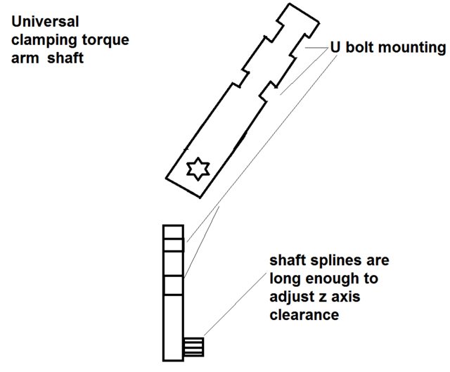
I've worked on a torque arm design myself, and have come up with a modular design to fit most bikes. Currently only for M12 axles, with M14 axle fit coming up.
What do you folks think of this one:

I make them in front and rear versions, and would be gladly sending some samples over for testing and evaluation if you are interested.
If you like more info, just read through the mounting instructions. There is a 3D explosion drawing in there as well.
http://electricwheels.de/torque%20arm.html
Jeez, it's getting late again...
Here in Germany we are just having a similar discussion in our forum, so you can imagine how I lapped up all the info
. Great work, Justin.I've worked on a torque arm design myself, and have come up with a modular design to fit most bikes. Currently only for M12 axles, with M14 axle fit coming up.
What do you folks think of this one:
I make them in front and rear versions, and would be gladly sending some samples over for testing and evaluation if you are interested.
If you like more info, just read through the mounting instructions. There is a 3D explosion drawing in there as well.
http://electricwheels.de/torque%20arm.html
Jeez, it's getting late again...
voicecoils
1 MW
electricwheels.de said:Just worked my way through 11 pages of postings regarding the testing of dropouts and torque arms.
Here in Germany we are just having a similar discussion in our forum, so you can imagine how I lapped up all the info
I've worked on a torque arm design myself, and have come up with a modular design to fit most bikes. Currently only for M12 axles, with M14 axle fit coming up.
What do you folks think of this one:
I make them in front and rear versions, and would be gladly sending some samples over for testing and evaluation if you are interested.
If you like more info, just read through the mounting instructions. There is a 3D explosion drawing in there as well.
http://electricwheels.de/torque%20arm.html
Jeez, it's getting late again...
What material is your 'securing tie' made of?
electricwheels.de
100 W
G'day
Depending on the use:
for Pedelecs a standard cable tie will do, PA 6.6, UV stabilised, up to 600 N pull
for e-bikes with some recouperation a stainless steel cable tie, up to 1100 N pull
for e-bikes with heavy recouperation (like braking) I'd use 2 torque arms, mounted in opposite directions.
Keep in mind that the mounting point of the securing band is about 110mm out from axle centre point.
Cheers
Reiner
electricwheels.de said:Just worked my way through 11 pages of postings regarding the testing of dropouts and torque arms.
Here in Germany we are just having a similar discussion in our forum, so you can imagine how I lapped up all the info
I've worked on a torque arm design myself, and have come up with a modular design to fit most bikes. Currently only for M12 axles, with M14 axle fit coming up.
What do you folks think of this one:
Hi Reiner, very nice work on that torque arm design, I like the style a lot.
I do agree with the question about the strength of the retaining cable tie, and this is the one piece that stuck out to me as a bit odd. It is true that in normal use, the torque of the motor driving forwards will cause the torque arm to rotate backwards and into the frame, so the tie is under no tension. However, when there is a fault with either the hall sensors or a shorted mosfet in the motor controller, then the torque can pulsate very heavily in both directions with significant jarring force, and I don't think that your cable tie could handle this.
In our original 2-piece torque arm design that used a single hose clamp to secure to the fork, we had I think 3 customer failures where the metal hose clamp actually tore in half from the forces that were present when they had a controller fault while moving at high speed in a direct drive motor. That's why we went to using two hose clamps in the current design. Part of the problem in our case is that the sharp corner of the waterjet cut stainless steel put a high stress location on the metal band, so if this was softened with a rounded edge then I'm sure they would hold up better.
Anyways, something to keep in mind. It's pretty easy if you are a bit brave to test this out by riding your bike with no controller and an ON/OFF toggle switch between two of the phase leads. Then, once you get up to a good speed (say 30-40 kph), close the switch to short circuit the motor phase wire and see if the torque arm holds the wheel in place or if it tears out. I'd wear a helmet and pads just in case! -Justin
voicecoils
1 MW
justin_le said:It is true that in normal use, the torque of the motor driving forwards will cause the torque arm to rotate backwards and into the frame, so the tie is under no tension. However, when there is a fault with either the hall sensors or a shorted mosfet in the motor controller, then the torque can pulsate very heavily in both directions with significant jarring force, and I don't think that your cable tie could handle this.
Yes, that's exactly why I asked
I know in theory, no cable tie at all would be necessary, but in practice unexpected things do happen!auraslip
10 MW
- Joined
- Mar 5, 2010
- Messages
- 3,535
It's pretty easy if you are a bit brave to test this out by riding your bike with no controller and an ON/OFF toggle switch between two of the phase leads. Then, once you get up to a good speed (say 30-40 kph), close the switch to short circuit the motor phase wire and see if the torque arm holds the wheel in place or if it tears out. I'd wear a helmet and pads just in case! -Justin
Do you pay hobos $20 bucks to test this for you?
This is why i think cable ties of any sort are a joke.
They will flex, bend, or even snap. They are not designed to handle dozens of ft-lbs of force.
A torque arm is only as strong as the thing at the end of it!
They will flex, bend, or even snap. They are not designed to handle dozens of ft-lbs of force.
A torque arm is only as strong as the thing at the end of it!
electricwheels.de
100 W
justin_le said:Next up was to try it with the wider 14mm axle. I only got 2 tests of this in, one with the nuts hand tight and the other with the nut tightened to 60 N-m.
Code:Nut Torque Axle Spinout Torque hand tight 49.5 N-m 60 N-m 79.9 N-m
Let's see what Justin does here. I will use rounded figures:
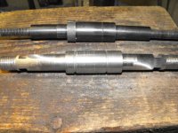
1) Justin is using a 14 mm diameter axle with 2 flat sides measuring 10 mm A/F
2) Justin is using 2 dropout plates made from 1/8" (or 3 mm) thick mild steel, with U-shaped (open) dropouts 10 mm wide, one @ each side of the axle. The axle shoulders lie flat against the inside surface of these dropouts, with the shoulder diameter measuring 20 mm.
3) The axle nuts being 'hand tight' means that the 2 dropout plates (with the U-shapes alone) can handle a torque of 50 Nm before failing.
4) After the axle nuts are being tightened up with 60 Nm of torque, the 2 dropout plates can handle a torque of 80 Nm before failing.
So far, so good.
Now lets do some calculating...
A) The axle shoulder diameter is 20 mm. The surface area of this diameter is 310 square mm, less the surface area (because it's really a hole) of the dropout U-shape of 160 square mm leaves us with a net shoulder surface area of 150 square mm per side. And because there are 2 shoulders, a total net surface area of 300 square mm where the axle is in contact with the dropout plates SIDES.
B) The torque of 80 Nm (see 4 - with the axle nuts tightened with 60 Nm) LESS the torque of 50 Nm (see 3 - with the U-shape alone) is the torque that can be handled just by the sideways pressure of the 2 dropout plates alone, which is 30 Nm. Or, if you want, a total pressure area of 300 square mm can handle a torque of 30 Nm... that means that 10 square mm can handle 1 Nm of torque.
C) Now let's look @ the U-shape of these dropouts.
The total thickness of both dropouts is 6 mm, and it can handle a torque of 50 Nm. That means that 1 mm thickness can handle 8 Nm of torque. Standard bicycle-frame dropouts are 5 mm thick, so 2 standard dropouts are 10 mm thick. 10 mm thickness can therefore handle 80 Nm of torque.
D) Look at the thing I call a torque-disc. It's a 4 mm thick washer that has the shape of the axle laser-cut out of it.
Now if 1 mm thickness of U-shape can handle 8 Nm of torque, a 4 mm thick washer can handle 32 Nm of torque coming from the axle. Because the torque-disc is pressed sideways against the OUTSIDE of the dropout by the axle nut (that has been tightened with 60 Nm), it can take 15 of these Nm (because the torque-disc is also 20 mm in outer diameter) and transfer them through this sideways friction (in the same way as the axle-shoulder does from the inside of the dropout) to the dropout.
Let's take a few figures here and add them up:
Torque taken from U-shape of 2 standard bicycle-frame dropouts - 80 Nm
Torque taken from 2 axle shoulders being pressed against inside of dropouts - 30 Nm
Torque taken from torque-disc being pressed against outside of dropouts - 15 Nm
As you can see can this setup alone handle 80 + 30 + 15 = 125 Nm of torque before failing!
Now, what else was there...? Ah yes, the torque arm itself, resting solidly against the frame of your bike.
My standard torque arm is, when all torque-discs are used and connected to it solidly by dowels, 8 mm wide.
If you look back to C), each mm of width can handle 8 Nm of torque, so all up this lever takes 64 Nm of torque from the axle and transfers it to the bike frame at a point 110 mm away from the axle.
Now add these 64 Nm to the other 125 Nm of torque, the total amount my torque arm setup can handle is 189 Nm of torque under acceleration!
Ah! Now for recouperation, or regenerating mode.
Lets take the Crystalyte Hx motor, and lets say it would under full load have a torque of (-) 100 Nm, minus because it is turning in reverse at this point in time.
Now, because the torque arm is drawn AWAY from the frame, we still have all the other bits holding 125 Nm of torque EITHER WAY, so we are still save.
And what about this tiny little plastic cable tie?
Well, work it out:
The cable tie can handle a pulling force of 600 N. M (torque) = F (force) x r (radius). So it's 600 N x 0.11 m = 66 Nm of torque.
That is in fact more torque that the torque lever can transfer from the axle to the frame (64 Nm)!!!
I would recommend a 48 V - 40 A system setup with a HS Clyte motor as ideal to go bashing through the bush with 40 kmh...
But hey - what if that motor suddenly blocks?
Well, in case of a front hub motor this shouldn't really matter to you, as everything that is happening in the vicinity of the axle will also be happening behind you ...
.And with a rear drive?
Well, don't really know. Guess the wheel will at first block, everything else is guesswork...
electricwheels.de
100 W
Aw, shucks!
I forgot that the torque arm is also pushed sideways against the dropout from the outside by the axle nut tightened with 60 Nm.
So add another 15 Nm to the total of 189 Nm, making it 204 Nm of torque it can handle before it (@ least in theory) succumbs to torque.
In practice I wouldn't push it that far
I forgot that the torque arm is also pushed sideways against the dropout from the outside by the axle nut tightened with 60 Nm.
So add another 15 Nm to the total of 189 Nm, making it 204 Nm of torque it can handle
In practice I wouldn't push it that far
LOWRACER
100 W
Similar threads
- Replies
- 9
- Views
- 1,081
- Replies
- 0
- Views
- 322
- Replies
- 10
- Views
- 1,231