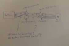
If you really need a manual disconnect (such as an antitheft measure, or fire-safety shutoff, etc) you could just use another of the same kind of connector you end up using for the battery connector in the first place (if you don't just bolt it directly in).
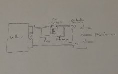
This second connector has one of it's shells mounted to the frame. The ohter shell gets a T-handle, and not connected to the frame. The frame mounted shell only gets the main positive cable wired to it, no negative. One contact of the FMS gets the main positive output from the battery, the other gets the main positive input to the contactor (assuming that's on the positive side like usual). The non-mounted shell just gets a loop of wire from one contact to the ohter. When you have it plugged in, it completes the circuit. When not, the system can't operate because it's missing the battery positive.
For myself, I'd use Anderson SB series for this, since they are made in many sizes, and genuine ones are good quality and will last a very long time even if you frequently cycle the connections (which you won't, for this, most likely--I don't cycle mine much but mine also all came used off of other equipment where I don't know their previous cycle life/usage). They come in two contact retention force options AFAICR, so the one for the battery you use the high-RF version so it can't come unplugged easily, and the disconnect one you use the low-RF version so you can more easily unplug it if you have to (becuase at the size you'd probably use, they get pretty hard to unplug). The shells are the same either way. You can also get keyed / color-coded shells, so different things using them cannot be connected incorrectly. They also make T-handles (and panel mounts, etc) which makes the whole disconnect-thing easy. Example pic found in google search:


Main two disadvantages to Andersons are cost and size--each shell will probably be about the size of a small pack of cigarettes, for a couple hundred amps version. (I use the SB50s, which are a quarter that size, and good for over 100A, but AFAICR they won't fit 0000 size wiring in the contacts (which are the same as those in the PP75), so you'd need the next size up at least--I think 6gauge is the biggest the SB50/PP75 contacts will take. I think the SB120 will take up to 1gauge).
The other disadvantage in some setups due to constrained space or routing limitations is the contacts must be able to "float" in the shell, so they can self-align during mating. If they can't, you can end up with only edge-contact, and a high-resistance connection that heats up and can even melt the shell, or start a fire. So you can't use wire with insulation so thick it fills the shell hole, and you can't route wires such taht they pull tangentially to the shell exit forcing the contact to twist or angle when connected. This is what usually gives Andersons a bad rep (besides the non-genuine ones having softer shells and weaker springs that allow this to happen even more easily), but is easily avoidable by simply routing and securing wires correctly.


") (you can DIY one, instead, but using one meant to drive a contactor is probably simpler).
(you can DIY one, instead, but using one meant to drive a contactor is probably simpler).