• Hello ES! We could use some help to get us past the finish line on building the new knowledgebase for the forum.
    Can you donate? Please see our fundraising page. Thank you!

Front wheel friction motor DIY

Ughetto

New here
Joined
Jul 25, 2025
Messages
9
Location
France
First of all, excuse my poor english. I red a lot on this forum about friction bike before daring undertaking anything.
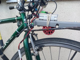
I want to add a friction motor to my touring bike. I tested a friction kit and found that 100 - 250 Watt is enough. The motor will be on the front rack. All this has to be lightweight and easy to fix (or throw away) . I must be able to keep the panniers on the front rack.
Motor brushless outrunner 6354 180KV 24Volts ...rated 1500W ( wich I doubt...but don't care ) 0.6kg
Controller : brain power KSLG 794 (should do the job) 0.2kg
LCD-S866
PAS left pedal 12 magnets. I had to change the bottom bracket (axle was too short).
No throttle, no Hall sensor on the motor.... keep it simple.
Battery will be à 7S3P , the motor is used only when it climbs. As this setting adds around 2.5kg and induces no drag, on the flat I am able to pedal.
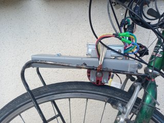
The result is ... ugly, crappy.... But it works (in my workshop with a small power supply) it is cheap, easy to fix.
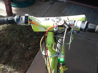
The lever on the stem allows the motor to engage and disengage. No sanding belt around the motor, will add some if it slips.
I will try to answer any question about this very low level prototype.
Joël UGHETTO
Motor_down.jpgMotor_up.jpgIf
 
The result is ... ugly, crappy.... But it works (in my workshop with a small power supply) it is cheap, easy to fix.
Beauty is in the eye of the beholder. I've seen maybe 3 or 4 friction drive ebikes over the years on the bike path. Rear and front drives, some using plywood. The one thing they all had in common is the riders were all grins, riding along in their own world at a leisurely pace and enjoying themselves.
Is the friction between the motor and tire just using gravity, or is there springs, etc. that I'm not seeing?
 
Tank you for your appreciation.
There are rubber bands hooked to the rack. They hold the controller and put some pressure. If it slips.. Add more rubber bands...and glue a sand belt around the motor... If they break, easy to replace and found everywhere.
I think, even with the weigh of the battery, wich will be in front of the controller, gravity would not be enough to get a good contact and in case of bump, I fear the motor could "jump" and slip, wearing the tyre if the motor is coated with sand belt. The position of the motor is such that it does not "engage in tyre" the way it does when the motor is under the crankset.
 
I admire the amount of ghetto fabulousness of this drive.
Looks like you are a hobbyking order and trip to home depot away from having a <$300 fricton drive.
There is a beauty in ghetto fabulousness.
 
I like it; you might want to read up on Kepler's thread for a lot of tips and tricks. It and a number of other useful threads are in this list Google search results

I tried two DIY friction drives years ago, and one of them worked pretty well, until I broke the motor shaft (for what were obvious reasons in hindsight :oops:) Both are in my DayGlo Avenger thread, if interested.


My main suggestion for the current design is, if you need to use a tension band like that, is to use a *good* marine-rated bungee cord instead of the rubber bands, because RBs will rapidly degenerate in sunlight, heat, etc. The bungee will also degnerate, but more slowly; the rubber bands inside it are a different material, and they are also covered in a thick layer of cloth, sometimes two.
 
I spent hours reading Kepler, Adrian and many others. Translating to french, summarizing... Trying to understand all the subtelties Thank you for the list.
Marine bungee cord would be a good choice... But I only had rubber bands in a drawer in my workshop.
Btw... the grey PVC part supporting the motor/controller/battery is a piece of tubing . Cut and flattened with hot air :rolleyes:... Yes, I know...3D printing existes or carbon mesh and epoxy resin .....But as long as low tech works, I will go that way.
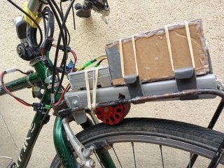

Once again thank you to this forum.
 
Work in progress. Added à "Mock cardboard battery" to check the dimensions. Sand belt around the motor, (imho more grip means less pressure to apply, better for the bearings). The bolten tabs at the back ensure that the motor remains centered on the tyre. The lever on the stem works well, I could probably modulate the pressure of the motor on the tyre instead of a ON/OFF system...
 

Attachments

  • Carboard_battery.jpg
    Carboard_battery.jpg
    476.8 KB · Views: 8
Tension was controlled by a lever-type shifter pulling down on the rear end of the rack plate, with it's pivot being one of the rack mounting tab notches hooked into the front edge of the basket.
1754032575128.png1754032590587.png
 
I have got a problem with the controller Brainpower and LCD 866 : Wattage and amper are always 0 ! I put a wattmeter in serie and found around 6 A and 150W wich is OK but 0 on the LCD.
Parameter P14 is supposed to limite the current ..but it does not work even at a low value of P14, the motor keeps running.
May be if no Watt and Amp are detected.... P14 cannot limit anything ????
PAS is detected correctly and the different levels of assitance seems to work .
 
I have got a problem with the controller Brainpower and LCD 866 : Wattage and amper are always 0 ! I put a wattmeter in serie and found around 6 A and 150W wich is OK but 0 on the LCD.
Parameter P14 is supposed to limite the current ..but it does not work even at a low value of P14, the motor keeps running.
May be if no Watt and Amp are detected.... P14 cannot limit anything ????
PAS is detected correctly and the different levels of assitance seems to work .
Do the voltage and battery levels read normal? Is this a new issue (power was displaying correctly before)?
 
Voltage and battery levels are ok. No error message.
It is a new controller and display for a home built friction bike by a total newby... eager to learn.
Thank you.
 
Voltage and battery levels are ok. No error message.
It is a new controller and display for a home built friction bike by a total newby... eager to learn.
Thank you.
There are no parameters for the LCD that would directly prevent the power from being displayed. The display would receive the signal for current/power through the Green (RX) conductor, since the display doesn't receive the current signal directly, but since the other functions work, it should be fine, but worth disconnecting the display harness and reconnecting it to make sure. There is one parameter P20 that's related to the communications protocol, which could be an issue. What is P20 set to currently?
 
All the last tests were donne in my workshop with a small power supply 24V.
I just received the battery... Put it on the bike.. Power ON level 0 .. Gain some momentum with my old leg ..Level 1... And wahou evrything works well . Speed, Amp, Watt.
Sorry for this wrong question and thank you for your help.
Pictures and results will come later !!! :)
 
All the last tests were donne in my workshop with a small power supply 24V.
I just received the battery... Put it on the bike.. Power ON level 0 .. Gain some momentum with my old leg ..Level 1... And wahou evrything works well . Speed, Amp, Watt.
Sorry for this wrong question and thank you for your help.
Pictures and results will come later !!! :)
Great! Now you can be one of those riders with the big grin on your face :).
 
Back
Top