magicmicros
100 µW
- Joined
- May 26, 2021
- Messages
- 8
Hey people!
New at the group here.
I'm Jesper, a Dane now living in Thailand.
Made my first e-bike about 3 years ago with a no-name controller and a 72V 20Ah battery.
No idea about top speed, at 70km/h, I had enough.
My second, which is about 2 years old, is based on a 2016 Kawasaki KSR150, which I stripped down and rebuilt.
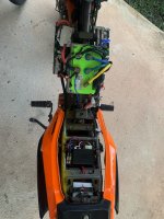
Controller and BMS is under the tank.
Battery is 96V, 48Ah (2 pack of 48V 48Ah).
12V battery is charged with a DC/DC from 96 to 13.8V through a no-loss "diode".
Motor is a QS138 90H V3, controller is a Fardriver NG96530 and BMS a JK Smart BMS.
Initially, I kept the original handlebars and made a 3D-printed throttle, using a slide pot and a spring.
Worked great for about 3000 km, were I replaced the handlebars and totally redid all of the bike wiring.
Motor mounting plates a laser cut from 5mm aluminum, front sprocket cover from 0.5mm stainless.
New gearing is 14 front to 56 back.
When I built it, I was excited by the potential. With the setup I would be able to push it to 30kW (for short peaks).
The original KSR had about 8 hp, 8.6 Nm, the EKSR about 45 hp, 500 Nm
Bike is a pocket rocket, it's trimmed down a bit to be manageable. I rarely use the top gear.
I calculated some performance numbers when I built it :
Top speed - 140+ km/h
0-100km/h - just under 3 seconds
Range - 95km
And, it fullfilled all expectations, except for range, that is about 80km (I might have underestimated my wind drag, or maybe I'm just a little conservative on when to charge).
The display is custom made, based on a ESP32 microcontroller the talks to the BLE on the controller.
I have posted in another thread about that with some technical details.
Questions welcome, of course.
/Jesper
My firstborn

Before

Almost naked

Old Throttle

Left

Right

Handlebars

Under the hood 1

Under the hood 2

Front sprocket cover with EKSR logo

Display (sorry for bad reflections)

New at the group here.
I'm Jesper, a Dane now living in Thailand.
Made my first e-bike about 3 years ago with a no-name controller and a 72V 20Ah battery.
No idea about top speed, at 70km/h, I had enough.
My second, which is about 2 years old, is based on a 2016 Kawasaki KSR150, which I stripped down and rebuilt.
Controller and BMS is under the tank.
Battery is 96V, 48Ah (2 pack of 48V 48Ah).
12V battery is charged with a DC/DC from 96 to 13.8V through a no-loss "diode".
Motor is a QS138 90H V3, controller is a Fardriver NG96530 and BMS a JK Smart BMS.
Initially, I kept the original handlebars and made a 3D-printed throttle, using a slide pot and a spring.
Worked great for about 3000 km, were I replaced the handlebars and totally redid all of the bike wiring.
Motor mounting plates a laser cut from 5mm aluminum, front sprocket cover from 0.5mm stainless.
New gearing is 14 front to 56 back.
When I built it, I was excited by the potential. With the setup I would be able to push it to 30kW (for short peaks).
The original KSR had about 8 hp, 8.6 Nm, the EKSR about 45 hp, 500 Nm
Bike is a pocket rocket, it's trimmed down a bit to be manageable. I rarely use the top gear.
I calculated some performance numbers when I built it :
Top speed - 140+ km/h
0-100km/h - just under 3 seconds
Range - 95km
And, it fullfilled all expectations, except for range, that is about 80km (I might have underestimated my wind drag, or maybe I'm just a little conservative on when to charge).
The display is custom made, based on a ESP32 microcontroller the talks to the BLE on the controller.
I have posted in another thread about that with some technical details.
Questions welcome, of course.
/Jesper
My firstborn

Before

Almost naked

Old Throttle

Left

Right

Handlebars

Under the hood 1

Under the hood 2

Front sprocket cover with EKSR logo

Display (sorry for bad reflections)

Last edited:

