How To Solder Your Own VESC!

I have access to 100W laser cutter. Which material is the best to use for solder stencil that can be cut with laser?
 
Stencils are usually made with kapton film or stainless steel. I have been getting much better results from stainless steel.

When using a stencil and reflow oven you can populate and reflow one side at a time. Many people think the components on the lower side during the second reflow will fall off. This is not true, solder paste flows at a much lower temp than solidified solder so the lower components hold fast. The only concern is that the pcb is level and you are following sufficient reflow curves for the solder paste you are using.

After reflow and depending on how well you applied your solder paste you will need to drag a hot iron across the processor pins to remove any bridges that may have formed. Simply drag excess solder to one side and remove any remaining with a solder wick. You may want to practice on something else to get a feel for it since you can bend a pin or worse, lift a pad off the pcb if you get too ham handed with this stage of the build.

I usually only attach the P2 JST-PH header before flashing firmware and initial motor testing. It is much easier to trouble shoot and re-drag pins to remove unseen bridges without all the JST headers in the way.
 
This still hasn't been done yet. So here we go.. Been meaning to revive this project and will continue on with it. :mrgreen:

Coming back alive!

I'm a newb but here we go trying to decipher the lingo.

- Benjamin Vedder's main page for VESC - The actual page with the main details for the VESC.
- Vedderb (github) - bldc-hardware - Here's the actual link to the BLDC Hardware files github page for Vedder's ESC (VESC).

Some of the info is a bit dated since we are now on v4.12 but the drawings and such on the frontpage are of the older version. I remember, Chaka mentioning about the C18 add on for v4.12 due to FOC issues. Still haven't pinpointed this exact detail yet as I haven't looked into the v4.10-v4.11 original drawings. We'll get back to that later.

Making The VESC PCB Boards

The VESC PCB Boards is a 4 layer PCB board and can pretty much be made anywhere. From Vedder's main page he's always mentioned to get boards from Hackvana (certain people have) the boards should be fine/great and the price is great as well. The second place to get VESC PCB boards would be OshPark. The PCB was created by Ben using KiCad.

1. Hackvana VESC
2. OshPark VESC

Using HackVana for PCB

hackvana%20vesc%20main.png


- Hackvana Wiki for VESC
- Hackvana PCB Q&A's

Here are the prices.
hackvana%20price.png


2oz copper can possibly be hard. Also seen here https://endless-sphere.com/forums/viewtopic.php?f=35&t=63540&start=350#p1008031

I'll start with the 1oz copper starting (since) I haven't soldered my own yet.

10 boards comes out to $100 + $30 for USA Shipping. That's a $10/each VESC PCB.

Make sure to ask for the v4.12.

OshPark PCB

- Vedder ESC v4.10 Uploaded By Chaka on Osh Park

This is for the v4.10. Cost is about $13/each VESC PCB.

You'll need to upgrade it to the latest version v4.12.
 
Some of the materials I'm not exactly sure if I'll need but I'll list it anyways for now. Any comments suggestions would be great.

Materials

Tweezers Set
6 pcs All Purpose Precision Tweezer Set Stainless Steel Anti Static Tool Kit - $4.99
http://www.ebay.com/itm/6-pcs-All-Purpose-Precision-Tweezer-Set-Stainless-Steel-Anti-Static-Tool-Kit-/331406774743?hash=item4d296211d7:g:pEMAAOSwD0lUgkl9

Magnifying Glasses
20X Watch Magnifier Jeweler Magnifying Eye Glasses Loupe Lens Repair LED Light - $6.99
http://www.ebay.com/itm/171655949354?_trksid=p2057872.m2749.l2649&ssPageName=STRK%3AMEBIDX%3AIT

Magnifying Lens
5X 10X 15X Triple Folding Pocket Magnifier Loupe Magnifying Glass Lens #ML26B - $5.25
http://www.ebay.com/itm/371098826005?_trksid=p2057872.m2749.l2649&ssPageName=STRK%3AMEBIDX%3AIT

Question - Solder Paste? What solder paste is best?


Here's some good videos..

[youtube]WDIqtGMROjM[/youtube]
 
Working on a couple VESC's for my upcoming rebuild, so far I have the MCU and motor driver on but for the rest of it I plan on taking a timelapse video of assembly. I've been using a hot air reflow station and a solder paste dispenser. unfortunately the dispenser is a piece of crap so ive gone back to hand dispensing the paste (grr) but I've done a couple boards this way. Hopefully when I get the timelapse up it'll be useful for anyone looking into assembling VESC's this way.


IMG_20160210_235135175_HDR.jpg
progress!


my never clean workbench, works well though
 
vesc_drv.png


I noticed on a few VESCs which I purchased these solder points weren't connected and some they were. What's the reason behind that?

Also for example on the DRV8302 - What's the 41CN10TG4 number? I've seen a few VESC's with different numbers?

Thanks for sharing.. Can't wait to share more.. What solder paste are you using? Any luck finding 500g?
 
The PCBs I got had those pads bridged, so the solder flowed into the area between and makes those two sets of pins bridged. As far as I know it should be fine (always double check the schematic though)

I believe with the drv8302, that additional number is batch/manufacturing codes, although I could be wrong

I picked up some chipquik solder paste, don't remember exactly what I got, I can update this post later with what I have.
 
Pins 50 & 51 as well as 53 & 54 are meant to be bridged: schematic.

Speaking from personal experience on my first 2-vesc run: after having soldered a bunch of resistors and ceramic caps, don't forget that C25 and C35 are Tantalum caps with a polarity.
Same thing goes for all the diodes, including the LEDS.
 
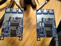
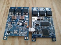
Two VESC's assembled! Just need to get some headers/connectors and a programmer and im all set.

[youtube]Z5JQ0EgvMs8[/youtube]
Here's a timelapse of assembly, bit more me in it than I was planning and unfortunately my camera's battery died before I completely finished but it turned out well.

close up of the finished boards:
IMG_20160216_093749990.jpg
 
Hi, for those interested in VESC 10pcs high quality four layer PCB's plus componentes to assemble 5 boards plus extra 6 MOSFET and many small components.
Please check http://goo.gl/rWNfr7
I've colected the best components directly from factory all genuine.
I do not have time to assemble due to work and university.

Any info please contact.
 
@Chaka: I saw that you very graciously posted your 4.10 gerbers for OshPark a while back. I am planning on placing an order to OshPark soon and I am going to try my hand at soldering a vesc (I am just going to be soldering one, but it seems like the cheapest option is still to buy 3 from OshPark :p ). I was wondering if you would be willing to post your gerbers for the 4.12 version? I figured I might as well do the most up to date version, but you said that you have to modify the files, and I would hate to screw that up and blow $40 for nothing! I am also going to be ordering the cap boards that you submitted a design for, may I ask what size caps you generally use for that? Again, a big thanks to you (and everyone else behind the vesc, esp. Vedder) for your willingness to share and help out the community.
 
torqueboards said:
560uF 63v for the Caps on the CapPCB and/or you can use a single 2200uF 63v if you didn't want to go the smaller 3 caps. Brand is Nichicon.

You can also find the files in the github and upload to Oshpark.

i had vesc crashes that disappeared when I used 2x 2200uF in parallel instead if 3x560! its a very similar form factor too! :eek:
 
Ptown_Cruiser said:
@Chaka: I saw that you very graciously posted your 4.10 gerbers for OshPark a while back. I am planning on placing an order to OshPark soon and I am going to try my hand at soldering a vesc (I am just going to be soldering one, but it seems like the cheapest option is still to buy 3 from OshPark :p ). I was wondering if you would be willing to post your gerbers for the 4.12 version? I figured I might as well do the most up to date version, but you said that you have to modify the files, and I would hate to screw that up and blow $40 for nothing! I am also going to be ordering the cap boards that you submitted a design for, may I ask what size caps you generally use for that? Again, a big thanks to you (and everyone else behind the vesc, esp. Vedder) for your willingness to share and help out the community.

Here's a link to my oshpark v4.12 files: https://oshpark.com/shared_projects/y0ye8b2o

I use three 680uf 63v capacitors with 5mm lead spacing on my builds. Get decent quality caps as others have had issues with cheap caps causing problems
 
I just soldered my first VESC. Bought boards at oshpark. Components at Mouser. HW 4.10. Successfully uploaded bootloader with ST-Link and "make upload" (got "verified ok" message in the terminal), then disconnected 6pin cable and connected VESC to the battery 5S LiPo (18.5V). Unfortunately it does not show any signs of life. No LEDs are blinking. How do I diagnose the problem? Where do I start?

Front:
fronts.jpg


Back:
backs.jpg


Larger images are here http://vedder.se/forums/viewtopic.php?f=7&t=195
 
rmrf said:
I just soldered my first VESC. Bought boards at oshpark. Components at Mouser. HW 4.10. Successfully uploaded bootloader with ST-Link and "make upload" (got "verified ok" message in the terminal), then disconnected 6pin cable and connected VESC to the battery 5S LiPo (18.5V). Unfortunately it does not show any signs of life. No LEDs are blinking. How do I diagnose the problem? Where do I start?

Front:
fronts.jpg


Back:
backs.jpg


Larger images are here http://vedder.se/forums/viewtopic.php?f=7&t=195

If you were able to load the firmware but get no response when powered you probably have some bridged pins. Check the usb, stm and the drv. I use a 10x loupe to check for solder hairs. If that fails you may need to reflow the drv chip and make sure it is soldered to the ground pad as that will also cause this issue.
 
So, how much money do you save by soldering your own VESC?
And where can you find a part list to every component you need?

Thanks, Nickzy_B
 
Back
Top