JD's BMC V3 Build - in progress

Great work with the terminations JD, and those cells are looking very safe and comfortable in that ammo box.
The bike's balance is a really good result. I look forward to seeing the big 28s pack with the X5.
Cheers,
Matt.P.
 
oatnet said:
I bought (4) WenTeq clamps that are used to mount lead weights on race cars. The inner diameter is 1.25" (32mm), perfect for the upper stanchions on Boxxer forks (<2010), with mounting holes for 1/2" bolts.
JD,
I just stumbled onto this build (can't believe I haven't seen it before). DMR has some hindged clamps but they're 31.8mm but may still work http://www.wiggle.co.uk/p/cycle/7/DMR_Hinged_Clamps/5220000003/
I'm thinking this mounting style would work well with the TF frames. Mount 4x6s Zippy/Turnigys (two on each side of the fork tube, long axis parallel with the ground, and controller in front of the headtube; forming a U around the headtube). You might even be able to stack three on each side.
Triton
PS Very nice build BTW
 
While I mount my packs on the frame as close to the headtube as possible, I agree that mounting them forwards instead of on the rear of a bike is a "game changer". Suddenly the bike actually handles like a bike again, and stupid stunt riding is possible :wink:
 
Matt, thanks for the kudos, Stay tuned :D

Triton, that is a great product. Apparently they are not readily available in the US for some reason, but I am thinking about importing a bunch. BTW, if anyone cares, I bought my "WenteQ lead weight clamps" from ebay seller "4raceparts" who offers them in 1.25" (32mm), 1.5" and and 1.75" flavors. http://cgi.ebay.com/ebaymotors/ws/eBayISAPI.dll?ViewItem&item=360266264657


John, I liked the idea of that location but my crude attempts were knee banging agony and awkwardness. With your skills, I am sure you crafted something much better.

OTOH, I like the feel of having the weight on the fork, the mass it acts as a steering damper. I expected to feel it exaggerating my motions, but it really just feels solid. I'd be unhappy if it felt like a basketful of loose groceries, I don't think I would like it if the mass could move around, and "bump steer". This just feels solid, like a nice german car. The pack gets the softest ride up there, plus I like to tell myself that with the stanchions taking the weight of the batts there is less pressure on the head tube (whether or not its true :D ).

The 15s3p a123 pack I originally built for this bike ended up on the back of a bike I built for my wife, which is featuring a rear Bafang you (John) built for me long ago. That motor left for Australia, never made it, and at long last ended up on this bike. Anyhow this bike is going to get the same treatment, using the smallest of the three ammo boxes below. I am also going to bolt the controller to her ammo box, and just run big phase wires and halls back to the motor. Everything else is local to the new controller location, throttle, CA, brake wires. I haven't figured out the best position for it though, it would be sweet if I could mount it between the box and the head tube but I don't think it will fit. I got a matched set of wheels using the DX-32 rim, 32 holes like, and put the front one on her bike. I had to get a centerlock Disk for it, 1st time on that hardware, I was glad to see it worked fit OK with my Avid BB-7 brakes.

View attachment 3

The middle ammo box is the same size as the one on the bike from this thread, and the large one is going to hold the (28s)100v/16ah pack of the a123 prisimatics. That one will have 6 clamps though. :D

1-lineup a-0057.jpg2-lineup b-0058.JPG

The front wheel on the BMC V3 bike is also a JohnRobHolmes creation. Hey John can you source that DX32 rim? I am thinking about getting another front wheel made...

file.php
 
Good work JD and happy to see the pack is working out well for you. Lots of very innovative ideas going on with your build, very cool
8)
 
Nicely done Oatnet!
 
Thanks for the kind words Paul and Luke! John, I'll be chatting you up soon when I sort out where I want to be on the 100v/100a 5305 build.

-JD
 
Nice job with the ammo cans! Super strong, waterproof, and cheap! What do they weigh? I may try a detachable front mount for my commuter bike.
 
Crystalyte-20A-ctrlr.png


I have a new suspension bike on the way to me (allegedly) and I was going to buy a V2 motor from Ilia so I could run a generic controller on it. I already have one of the controllers in the pic above, and this new bike has a spot where I _might_ be able to conceal it very well. If it does fit when the bike gets here, I'll probably go with the V2 and put the V3 back on the IO frame. But if I have to conceal a regular controller, I realized I could just as well use my V3 instead...

It has been @ 5 months since I opened the V3 to replace the melted phase wires. I spent a bitch of an afternoon jamming new phase and hall wires through the )(*&#$%*(*)(@#$ too-small axle hole, and when I was done I was so frustrated by the process I let it sit.

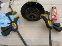
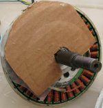
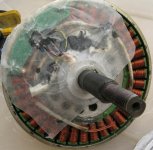
I think what really constipated the process was trying to find the right high-temperature epoxy to hold the phase wires down, yet not so permanent that I couldn't chip it off if I melt the wires again. I eventually PM'd Dr. Bass, who said I should get a high-temp silicone instead... so I procured some high-temp gasket silicone from Ace hardware yesterday. Today I soldered the halls and phases back on, and applied the silicone. On top of that I put a layer of wax paper, and a circle of thick cardboard, and clamped down the motor cover down on top. Hopefully, the cardboard will press the wires clear of the motor cover while the silicone drys, and the wax paper will keep the silicone from sticking. In 24 hours I'll undo the clamps and see if the silicone cured despite the wax paper, and see if it spins up.

Next, I need to do Ilia's CA/throttle mod to the controller, so I don't have to replace the phase wires again:

 
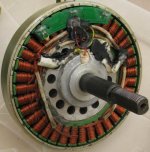
I opened the motor today, and the wax paper peeled right up as had I hoped. The high-temp silicone felt a little soft, so I think the wax paper kept it from completely curing, and I'll have to let it sit another day without the wax paper. However, it is solid enough to maintain shape and secure the wires to the stator, so it doesn't need the wax paper/cardboard/compression anyhow. A few spots of bare wire at the hall sensors were still exposed so I put a few dabs more of silicone there since I was gonna leave it out anyhow.

I realized that I probably should have run the hall/phase wires through the nuts and the wheel before running them through the axle. I am going to cut the phase wires down anyhow, and splice them onto heavier gauge, but cutting off the hall connector is extra work. It may be worth it to not have to have had it connected to the wheel when I was trying to jam the @#$()*@ wires through the axle. Besides, I can still use the connectors as a test before I bolt everything back together.

I got the BMC controller off the bike and opened the case today, if I get some time, I might solder on the CA connector and throttle interface per Ilia's instructions. Anyone know the specs on the diode I should use?

-JD

0 unclamping IMG_1538.JPG

1 cardboard IMG_1539.JPG

2_ wax_1540.JPG

3 open IMG_1541.JPG

 
Ya never know what you will find when you try to open a new type of controller, but the BMC is straightforward, no power switch wires to clip like the old xlytes...

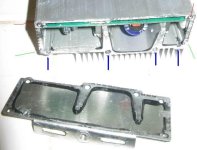
First, you need to remove the the end-cap without the wires. Remove the screws indicated by the red lines and thick blue lines. On the side with the wires, just remove the screws indicated by the red line. I commend BMC for doing an excellent job of weather sealing their controller, although it did make getting that first end cap off - I had to put the tip of a flat-head screwdriver into one of the heatsink grooves, and tap it with another tool.

5_End Cap IMG_1544.JPG

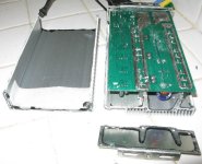
Next, the case lifts right off - the area indicated by the green lines in the photo aboves shows where it joins together. One of the better built cases I have seen.

6 open IMG_1545.JPG
 
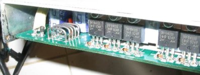
I remember adding solder the base of a controller's shunts to decrease its resistance, and increase the amps. I assume the opposite is true, and In the case of the BMC 50a and the V3, I want to Decrease the amps.

Here is a picture of the shunt side of the controller. I see 5 shunts in this 50a controller, and I believe each one represents 10a of current. If I lifted or cut (2) of these shunts, wouldn't I be limiting the controller to 30a, without the use of CycleAnalyst?

I'll still hook up a CA, but then I don't have to depend on it for control. I know Ilia said 35a was good for the V3, but I'll be hard on this build, so I was already planning on running 30a for an extra safety margin. If I cut the shunts from opposite sides, in theory In the future I could solder them end-to-end to approximate 35a...

I don't need to do it this very moment, but unless anyone points out a fatal flaw I thing I am going with this approach. Comment welcome! :D

7_ shunts_IMG_1543.JPG
 
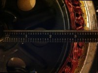
Inside the 9c, the straight edge is against the axle where it is .675" diameter, so add .3375 for actual.

-JD
 

Attachments

  • IMG_5870_FLIPPED.jpg
    IMG_5870_FLIPPED.jpg
    85.4 KB · Views: 3,312
Just following that you said it may be simple, I'm thinking about maybe only buying the cells. Have few questions:
- What tool did you use to crimp the tab?
- Where did you find the crimps to use?
- And where to find a good bms for A123? I'm looking for a 20s set up.
- And do you recommend Victpower cells?

Thanks a lot
 
cwah said:
Just following that you said it may be simple, I'm thinking about maybe only buying the cells. Have few questions:
- What tool did you use to crimp the tab?
- Where did you find the crimps to use?
- And where to find a good bms for A123? I'm looking for a 20s set up.
- And do you recommend Victpower cells?

Thanks a lot

1) Large Electrician's Pliers.
2) The crimps are not additional hardware - just the tabs folded over 3-4 times, crimped flat after each fold, so that both sides of both tabs are in direct contact with each other.
3) I don't use a BMS on LFP.
4) I bought (110) cells from VictPower and I thought they were great. I found (1) with the tab at an odd angle.

-JD
 
Thanks for your answer, but if you don't use BMS, how do you balance your pack?

I heard that A123 needs balancing isn't it? And you may also do deep discharge or overcharge sometime isn't it?
 
cwah said:
Thanks for your answer, but if you don't use BMS, how do you balance your pack?
I heard that A123 needs balancing isn't it?

I use single cell chargers when I balance packs - there are extensive threads on this. For the pack above, it was (2) years before I gave it it's first balance charge:

http://endless-sphere.com/forums/viewtopic.php?f=14&t=40422#p590800
"I was on vacation last week, and one of the things I did was install
andersons on the balance wires on the pack in this bike, and gave it its
first-ever post-build balance. 19 of 20 cells reached full charge within
a minute of each other. (1) cell took another 8 minutes.

I typically parallel then balance all of the cells used on a pack, on one
single cell-charger, and let them sit on trickle charge for about a day.
Then I build a pack from them.
"

And you may also do deep discharge or overcharge sometime isn't it?

Note that the 3000 cycle rating on a123 is to 100% DOD.

Despite that, I size my packs to avoid deep discharge, but when I know I might have one, I _will- do a single-cell balance charge before the ride. My style of protection won't work for everyone. I baseline a pack so I know what WH I can expect from it, and get a feel for the discharge curve, and monitor WH and V on my CA. If the pack drops V early, I usually feel it first anyhow.

I monitor my packs during charging, and I haven't had an overcharge in 5+ years. I can see how a failed cell might lead to an overcharge - but in a 20s pack, the smallest I have, a failed cell would overcharge the remaining 19 cells up to 3.84v/cell, not a big deal for a123. Losing 2 cells - 10% of the pack - would go to 4.03v/cell, more than I would like, but probably still OK.

If I used LiCo, I would definitely use battery monitors and BMS, because mistreating the cell can lead to thermal runaway, fire, injuries. By contrast, In my experience, draining LFP to 0v leads to flat cells, so the major risk is wasted money on dead cells. I have saved far far more money by forgoing the BMS, than the cost of cells I have killed by being stupid. As I said earlier though, my method will not work for everyone, you have to be as meticulous as I am.

-JD
 
You're as cautious as if you were using lipo with A123.

I don't have BMS with my lipo and I carefully monitor the charge/discharge. And to get a bms for lipo is quite expensive. The only simple one to get is from Methods and is quite expensive.

The advantage of A123 is the simple plug and play. Plug it, let it charge, then come back and it's ready!!
 
Back
Top