jonescg's NEW electric racebike BUILD thread!

Potting is mainly to keep the cells snug in their capture plates so they don't vibrate themselves to pieces. But also waterproofing/corrosion resistance, and a bit of thermal uniformity.
Well, the foaming silicone would do that, and be significantly lighter than solid potting...but I don't know of one with any longer pot life. :(

I hate hate hate short pot-life polyurethanes. Like you I'm just too slow at doing the mixing and pouring.
Yeah, if there was another foaming silicone (it's not a PU) I could use, I'd do it. But there isn't any other with a longer pot life that I can find. I usually use their regular stuff like DragonSkin, etc., which gives you about a half hour to work with it, so I can add dyes and get colors just right, work it down into molds, etc. But sometimes I also need something that has a lot of squishiness, like a foam, and this is the only stuff that really bonds with the other stuff (if you cast the one over the other right after casting the first).
 
Chris, are you going to weld these or ?

On the pack I'm working on (two stacks of 30S13P), I split each 30S stack into two sections: 16S and 14S and plan to incorporate a 3/8" polycarbonate spacer between the two sections. I'm welding (kWeld with copper sandwich technique) and using cell holders. I put two dabs of caulking between each cell all the way around the exterior which stiffened them up a lot. The 3/8" spacer will have some inserts installed so that section can be braced to the outside wall of the pack at the ends i.e. not through the copper and that should stiffen it up some more, so I'm not planning on using any potting.
 
Hi Frank,
I'm going to continue with the copper busplates and soldered nickel links. Then I spotweld the links to the cell ends. It's been really solid so far, and far more adaptable to unique configurations. The holes in the bus plates are about 15 mm diameter, so there's plenty of room for the tab. But the key step is to plaster the faces with thermally conductive epoxy resin and a 0.8 mm thick layer of G10FR4. Makes the whole thing rigid and waterproof, but potting will help if its runny enough.
 
Looks like I'm about to get busy!
20230712_120939.jpg
Just arrived today. A bit spendy - maybe $500 AUD/kWh landed. Probably just means they're legit.
 
I can’t tell whether you’re about to build a battery for your motorcycle or you’re about to open a made-to-order battery shop.
Since he's already done both of those, I can see how it would be tough to tell. :)
 
So the cell arrangement and busbar layout is done. Just need to save up some money to get the capture plates and busbars cut.
Voltron cylindrical pack layout and busbars.jpg
Then to make four of these...
 
It will actually be less of a beast than before, but should be able to manage twice as many laps.
What real world C-rates are folks seeing from these Molicells? Because at 45 amps per cell, I'm looking at about 140 kW. We got about 180 kW from the pouch cells, so outside of Philip Is or Queensland Raceway, we won't really notice the difference.

Well it is not straightforward since there is a lot of peak loads and I assume some high current regen. I would monitor cell temps in real world race and adjust battery current based on that. 25-30A cont per cells should not be a problem, but that is not representative of real world and as you've said 45A or even a bit higher peaks should also be fine.
 
Well unfortunately the nickel tab becomes a bit incandescent at 35 amps, so I have my doubts about much more than 100 kW actually.
I'd need a much bigger spot welder if I wanted to weld copper tabs to the cells. Sunstone offers a 250 J welder, but I can't see me making that sort of an investment. Battery Copper Tabs
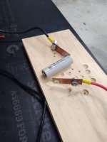
Cell under test.jpg
 
Well 0.1 x 6 mm nickel got red hot at 35 A.
I tested some 0.2 x 8 mm nickel and it got red hot at 65 A.
Cell under test 02 mm Ni.jpg
So I think 45 A is a best case scenario here...
 
Well unfortunately the nickel tab becomes a bit incandescent at 35 amps, so I have my doubts about much more than 100 kW actually.
I'd need a much bigger spot welder if I wanted to weld copper tabs to the cells. Sunstone offers a 250 J welder, but I can't see me making that sort of an investment. Battery Copper Tabs
Heh- thanks for doing us all the favor of making a nickel strip glow at 35A.

Maybe I’m missing something about a build constraint, but why not just nickel-copper-sandwich your tab connections? I’ve never seen anyone from the hobby world put together a 100kw capable battery from round cells, but the technique works well enough for us commoners wanting 50 or 100-odd amps to pass through their battery.
 
Well 0.1 x 6 mm nickel got red hot at 35 A.
I tested some 0.2 x 8 mm nickel and it got red hot at 65 A.
View attachment 336629
So I think 45 A is a best case scenario here...
I’m not the most knowageable person in the room, here— but I’d be shocked if you can reliably and routinely pass more than 25amps through a .2x8mm piece of nickel.

Matadors ampacity chart conservatively rates that bussing at 6.4amps. Shouldn’t be a problem to pass more than that, but I’m skeptical about how well it’ll hold up at multiples of that figure.

I fear that once this battery gets wrapped up and insulated, all those strips will build heat together. On the flip side, everything will be connected to a large thermal sink of thick copper plate. But heat generated is energy wasted in any scenario.

My two cents & maybe I’m missing something altogether. Excited to see this project come together and kick ass. Thanks for sharing as you’re working on it!
 
It's a constraint I've long known about - that nickel is 5 times as resistive as copper. For the car conversion I used this technique and it's been great, but the cells are passing less than 10 amps peak, and more like 2 amps under normal loads.

A race bike is a different proposition. This is lap one, back straight, max power:
Max Power.JPG
and it was over 160 A for about 8 seconds. So on this pouch cell battery we're looking at a peak of 27 C, and over 10 C for 8 seconds.
So on a battery with less power you'd be asking more of it, for longer...
 
Maybe I’m missing something about a build constraint, but why not just nickel-copper-sandwich your tab connections?
I have copper adhesive foil I can stick over the nickel. I mean, that might help right?
 
20230716_203404.jpg
It sounded so stupid I had to try it... And, it kind of worked! Pulls 100 A before glowing red hot.
 
Hehe, unfortunately my 12 year old DeWalt cordless drill is still chugging along, so I still can't use the interchangeable battery system.
I've made enquiries with Sunstone about finding an Australian business who has recently purchased a pulse arc welder. If there's one locally I might try and get the battery pack welded up using 0.2 mm x 8 mm copper. Otherwise the 0.2 mm x 8 mm nickel will be my only option. And the copper tape is too hard to ensure reliable contact, so I think that's the wrong path.
 
An update to the copper tape story - I read on another thread here on the 'sphere that you can spot weld a nickel-copper sandwich with a regular resistive welder. As you can see from above the copper tape definitely helped, but it's not exactly consistent.
So this afternoon I decided to try welding the copper side of the bi-metal tab to the cell can... and it actually worked surprisingly well. I only used the 8 ps setting on the Sunkko welder (higher than I would use for nickel, but not huge) and it took some effort to peel it off.
The proof was in the discharge test though, so I repeated the experiment above and managed to pass 60 to 55 amps for a good 7 seconds and virtually negligible heating of the tab! I could hold it with my fingers as it discharged at nearly nearly 15C.

So while a pulse arc welder might to a tidy job, for a one-off project like this I think the copper-nickel tab might work.
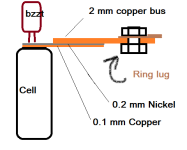
For reference the copper is 0.1 mm thick, and the nickel was 0.2 mm thick, and 8 mm wide. The adhesive smokes a bit when you weld it...
 
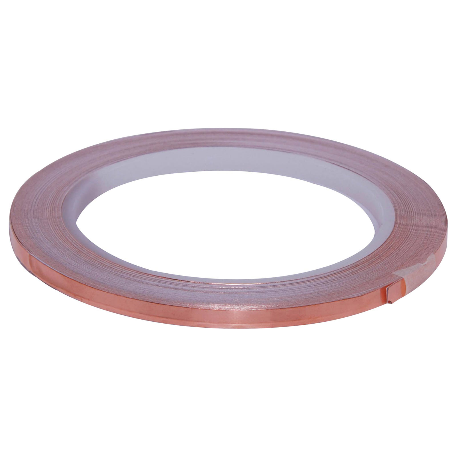
So youre saying the layers were copper tape->nickel strip->cell body? Do you have a link for that copper tape w adhesive?
 
So youre saying the layers were copper tape->nickel strip->cell body? Do you have a link for that copper tape w adhesive?
spotwelding solution.png
No, nickel, then copper, then cell. According to this the tape is 0.07 mm, but the adhesive was probably the rest.
 
View attachment 336799
No, nickel, then copper, then cell. According to this the tape is 0.07 mm, but the adhesive was probably the rest.
The diagram made my day, thank you. You see, I was wondering what the red oval on the top right could possibly have been. Luckily, you remembered to correctly label it with a BZZT.
 
Many people have had success with copper-nickel sandwich builds, myself included. I found that I had to kick my KWeld into 120J to get .1mm copper to weld as well as I’d like, but I read others are able to pull this off with less power. I really want to see the copper tear when yanked on.

Either way, you can definitely get copper onto a battery can successfully with affordable DIY tools. I’ve read of people welding .2mm copper successfully, but I’ve never needed to try because I don’t need that much conductor.

At 160A from a 5P battery, you’re pulling 32A a cell. By the data sheet, a P42A cell should deliver, and you’d move your heating limitation from the tab to the cell, which is more ideal.

Most of us don’t push our cells this hard- I use high discharge cells to limit sag, not because I need all those amps. Again, following keenly. Great work so far.
 
Back
Top