
Hello everyone. I have 9FET KT controller (22A/48V) with the original firmware from KT and I am trying to figure out how much phase current it can supply. I need that in order to calculate the torque of my motor as I am overvolting it. I see on the board there is some shunt on one of the phases and since it's a torque sim controller I guess it's using the phase amp to make possible the torque sim. Do you know in what range is the phase current of these controllers with the original KT firmware? Like 2.5x the battery current or so?
You are using an out of date browser. It may not display this or other websites correctly.
You should upgrade or use an alternative browser.
You should upgrade or use an alternative browser.
KT motor controllers -- Flexible OpenSource firmware for BMSBattery S/Kunteng KT motor controllers (0.25kW up to 5kW)
- Thread starter casainho
- Start date
I had a phase current amplitude of 70-80A.nikolay said:Do you know in what range is the phase current of these controllers with the original KT firmware? Like 2.5x the battery current or so?
https://endless-sphere.com/forums/viewtopic.php?f=30&t=87870&p=1426630#p1426630
Blik86 said:I had a phase current amplitude of 70-80A.nikolay said:Do you know in what range is the phase current of these controllers with the original KT firmware? Like 2.5x the battery current or so?
https://endless-sphere.com/forums/viewtopic.php?f=30&t=87870&p=1426630#p1426630
Thanks. I expected it around 50-60A max. The torque on my Bafang motor is rated at 32Nm. With 80A it will be double so pretty easy to strip the gears... Do you know any way to control the phase current with KT firmware - there is option for the current (C3 as far as I remember) which can be configured with so called "slow start" with one, two or three levels? I guess this can be used to lower the initial torque i.e. the phase amps.
Also I see on your oscilloscope graphs now 70-80 is peak (like 700-800 mV). However in the calculations for torque of motor simulator aren't these phase amps RMS? I am not so good with these motor theory but it's logical it's RMS not peaks of current. On your graphs RMS goes up to 40-50A which is more acceptable.
Perhaps in the original, it can give out more than 70-80A, but it will surely get hot even from lower currents. C5, but I didn't watch it.nikolay said:Thanks. I expected it around 50-60A max.
I don't understand the simulator. In my understanding, there are 3 phases in the motor .... if you count the rms, then for 3 phases with 80A amplitude. Again, if the motor is blocked, a direct current of 80A (80A rms) will flow.
How did you measured this currents? By connecting the probe to the current sensor output I guess? And it was a bench test without load on the wheel - you just spinning unloaded? There is only one current sensor on one phase but on the Y 3phase connection in order to measure the current you need two. Grin simulator just says "motor current" but this should be the RMS. Correct me if Im wrong but if rms is 40A and you double that the total motor current will be indeed 80A for some short time...
My next question is - if I pickup the voltage from the single current sensor connected on one phase and connect it to osciloscope or MCU how to interpret this signal ? For example - double it over 1s, do RMS calculation and got the real current flowing to the motor? Is this the correct way?
My next question is - if I pickup the voltage from the single current sensor connected on one phase and connect it to osciloscope or MCU how to interpret this signal ? For example - double it over 1s, do RMS calculation and got the real current flowing to the motor? Is this the correct way?
Measured Tektronix A622, current in green or battery (13s) wire. The voltage is about 50-52V.nikolay said:How did you measured this currents?
I loaded the wheel with a disc brake, in time it is a couple of seconds and the controller turns off the motor (8fan bpm 10t). Pictures for the initially locked wheel and rotating with the subsequent blocking (see the name of the pictures).
The output of the sensor is unipolar, you first need to subtract the midpoint. If you just want to estimate the value, then with a rotating motor yes. For something more this is wrong.
sylvain_wm
100 mW
- Joined
- Feb 2, 2020
- Messages
- 47
Hi there,
I've got a 18FET controller and I was wondering if anyone knows the max current frequency that is provided by this type of controller.
I'd like to increase the max speed, but it doesn't work. So I think it's because of the frequency of the PWM signal?
I have a LCD8H and a 1000W XOFO hub motor.
Has anyone faced the same issue?
Have a good one.
stancecoke
1 MW
sylvain_wm said:I'd like to increase the max speed, but it doesn't work.
I think the 1000W XOFO is a direct drive, this will never reach the max erps limit.
I think in your case the speed is limited by the battery voltage. You have to use a Battery with higher voltage to get more speed.
Another option would be field weakening, but this a little bit tricky with the open source firmware. You can adapt the value of "correction angle" but this will decrease the efficiency, as it shifts the advance angle at all speeds, not only at high speed.
regards
stancecoke
sylvain_wm
100 mW
- Joined
- Feb 2, 2020
- Messages
- 47
Thank you for your answer.
My XOFO hub motor is a geared hub motor.
I think that there is a limit somewhere in the program that prevent the inverter from increasing the frequency of the motor voltages. Or maybe the frequency reaches a too high value for my motor? I have no datasheet for this motor.
I have a torque sensor connected to the throttle input and the PAS input.
But I don't understand the program, I don't know where is the torque control.
As the matter of fact, I guess I'm a bit lost.
Have a good one.
eLsc
100 µW
- Joined
- Jun 22, 2020
- Messages
- 7
Hi there,
So I've been using this firmware on my daily commute and so far everything has been pretty good, still having to figure out some things but nothing a bit of tinkering can't fix (better angles :wink: ).
Lately the controller has been giving me some trouble, as something seems to crash while riding, resulting in the motor running at the speed it was when this happens, sometimes forever, sometimes for like a minute, then it resumes working. It seems it happen more frequently when the battery is about half empty (about 33 V).
I'm really confused by this as I can't pinpoint where this is coming from, as there has to be something running in the controller for it to have the motor running at a constant speed, but not reacting to any inputs/stopping the motor.
My primary Idea was that the 5V rail can't keep up with the demand (drops to about 4.3V - 4.0V) of everything attached ("only" Controller, Hall sensors, Throttle and PAS, Bluetooth module on separate step down supply) and as the VOUT rail and 5V rail have a not so good design with that resistor in front of everything as well as the Voltage regulator, I was thinking about replacing the 5V rail, also to relieve the Voltage regulator infront of it.
1. Is this a good idea/has anyone else have had similar problems
2. Am I on the right path, as I am generally more the Hardware guy and do not understand what is going on inside the controller to a full extent
regards,
eLsc
stancecoke
1 MW
you just have to activate the checkbox "torquesensor" and enter a appropriate value for TQ Calib. Of course Throttle min and Throttle max must be fitted to your sensor. Number of PAS magnets (Pulses per crank revolution) should be correct, too.sylvain_wm said:But I don't understand the program, I don't know where is the torque control.
If you don't know the gear ratio of your motor, I can't help. The ratio is the most important parameter to judge, if the max erps setting or the battery voltage limits the speed.
regards
stancecoke
Iambuilderman
10 W
apple2 said:I am new to this but yesterday managed to compile the code with no issues except that I had to comment out the following lines from the makefile-windows:
# @$(ENTF) *.asm
# @$(ENTF) *.rel
# @$(ENTF) *.lk
# @$(ENTF) *.lst
# @$(ENTF) *.rst
# @$(ENTF) *.sym
# @$(ENTF) *.cdb
# @$(ENTF) *.map
# @$(ENTF) *.elf
# @$(ENTF) *.adb
It used to get stuck on the cleaning stage and not progress to compiling. I am not sure why these are in the makefile just after clean.bat which does the same.
Anyways, instructions are good if I managed to do it. Thanks for that.
I also fitted the 72v 18fet sinewave controller to the bike and ran it with the standard firmware to make sure halls and phases are wired right.
Also overvolted it to 24s (100v) with the only modification beeing fitting a dc-dc switching regulator instead of the lm317s. Caps and mosfets beeing rated at 100v seem to be doing just fine after 1 day of riding.
Now before flashing the firmware I have a few questions:
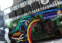
1. Is the firmware compatible with the 72v 3kw 18fet controller? It has the current sensor on one of the phases.
2. How does it perform compared to the stock formware? The notes say something about block commutation not available yet. I can feel the motor currently starting in non-sinewave mode and then switches to noiseless shortly after.
3. Does it show battery voltage on LCD3?
3. Do I need to reflash LCD3 with alternative code?
Thank you for your help. Although not a programmer by trade I have some experince and I am looking forward to understanding the code and possibly helping improve it as much as I can.
Hello guys,
Great to see all this good work around the kt controllers.
I myself would like to upgrade my 18 fet 48v kt controller to allow for up to a 72v 20s battery. I know many of you have tried or done this before, but I cannot find a complete overview of the steps to take. I already have ordered the following:
- low esr 100v 1000uF caps
- 50 pieces irfb4110 100v mosfets (“original disassembly”)
I need the following information:
- schematic of the location and pins of the components on the pcb of the 18fet kt controller
- I am planning to bypass the lm317s (if I know where to find it) with a dc-dc converter. Does it need to supply 15v or could this also be 12v?
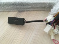
- I would really like to use a Bluetooth dongle instead of my current kt-lcd3 Display (48v). How do I make sure I supply the correct voltage to this dongle/display connector? For simplicity, I would also like to use a dc-dc converter for this.
- what other components do I need to upgrade to enable 72v (84V peak) battery voltage?
I am sure more users have the same questions, so if somebody can provide feedback on the missing info that would be highly appreciated!
Also, I am interested in doubling the mosfets for a higher amp rating, as I will soon have plenty of fets lying around. Did anyone suCees in making this work by now?
Hoping to squeeze as much cheap power from this nice controller as possible!
sylvain_wm
100 mW
- Joined
- Feb 2, 2020
- Messages
- 47
stancecoke said:you just have to activate the checkbox "torquesensor" and enter a appropriate value for TQ Calib. Of course Throttle min and Throttle max must be fitted to your sensor. Number of PAS magnets (Pulses per crank revolution) should be correct, too.
If you don't know the gear ratio of your motor, I can't help. The ratio is the most important parameter to judge, if the max erps setting or the battery voltage limits the speed.
Thank you, I'll try to change this paramaters.
Regards.
Sylvain_wm
tenten8401
1 mW
- Joined
- Aug 22, 2020
- Messages
- 16
So, since posting last time I've gone ahead and ordered an ebike kit with a KT controller. I've been informed it's a square wave controller, but the wiki says it's possible to retrofit phase current sensors onto most boards, but I can't find anything on it so far. Does anyone have anything that could point me in the right direction here? Would love to use the existing cheaper controller and install some parts than just throw it out and buy a sine wave model..
In addition to this, is the retrofitting only available for the open source firmware? I'd like to run it but after I ordered I realized it said that LCD8H isn't compatible at all due to a missing clock or something.. If I retrofit a phase current sensor onto a square wave controller will the proprietary firmware that comes with it pick it up and use it? Is there anything I can do to get LCD8H working on the open source firmware?
Sorry for all the questions.
Davidcroatia
100 W
- Joined
- Jun 23, 2020
- Messages
- 180
What is the best 48v 52v kt controller from aliexpress 1500w or maybe 2000w
tenten8401
1 mW
- Joined
- Aug 22, 2020
- Messages
- 16
Also, related to post above, what part number is the phase current sensor for the 48v kt controller? Can barely see it in the pics.. If someone with a sine wave controller could pop theirs open and get a part number it'd be greatly appreciated ")
Edit: Nevermind, found it.. ACS758LCB-100B-PFF-T I think
Edit: Nevermind, found it.. ACS758LCB-100B-PFF-T I think
tenten8401 said:So, since posting last time I've gone ahead and ordered an ebike kit with a KT controller. I've been informed it's a square wave controller, but the wiki says it's possible to retrofit phase current sensors onto most boards, but I can't find anything on it so far. Does anyone have anything that could point me in the right direction here? Would love to use the existing cheaper controller and install some parts than just throw it out and buy a sine wave model..
In addition to this, is the retrofitting only available for the open source firmware? I'd like to run it but after I ordered I realized it said that LCD8H isn't compatible at all due to a missing clock or something.. If I retrofit a phase current sensor onto a square wave controller will the proprietary firmware that comes with it pick it up and use it? Is there anything I can do to get LCD8H working on the open source firmware?
Sorry for all the questions.
It's either going to be an ACS711 or ACS712 depending on the controller. The chip is also tiny. If you have the LC package (8 contacts), you might be able to solder it on with a normal soldering iron. If it's the EX package, it's going to be a nightmare to solder it on without a hot air station. I've tried to solder on the EX package with a soldering iron and a tiny conical tip. It's a nightmare and the first time I tried I ended up shorting the motor phase to the STM8 IC (40v tends to break stuff that doesn't expect more than 5).
Here's the datasheet for the ACS711: https://www.google.com/url?sa=t&rct...tasheet.ashx&usg=AOvVaw1skxHMCQ6ZeM1zeS3EAjUf
tenten8401
1 mW
- Joined
- Aug 22, 2020
- Messages
- 16
KonKey125 said:tenten8401 said:So, since posting last time I've gone ahead and ordered an ebike kit with a KT controller. I've been informed it's a square wave controller, but the wiki says it's possible to retrofit phase current sensors onto most boards, but I can't find anything on it so far. Does anyone have anything that could point me in the right direction here? Would love to use the existing cheaper controller and install some parts than just throw it out and buy a sine wave model..
In addition to this, is the retrofitting only available for the open source firmware? I'd like to run it but after I ordered I realized it said that LCD8H isn't compatible at all due to a missing clock or something.. If I retrofit a phase current sensor onto a square wave controller will the proprietary firmware that comes with it pick it up and use it? Is there anything I can do to get LCD8H working on the open source firmware?
Sorry for all the questions.
It's either going to be an ACS711 or ACS712 depending on the controller. The chip is also tiny. If you have the LC package (8 contacts), you might be able to solder it on with a normal soldering iron. If it's the EX package, it's going to be a nightmare to solder it on without a hot air station. I've tried to solder on the EX package with a soldering iron and a tiny conical tip. It's a nightmare and the first time I tried I ended up shorting the motor phase to the STM8 IC (40v tends to break stuff that doesn't expect more than 5).
Here's the datasheet for the ACS711: https://www.google.com/url?sa=t&rct...tasheet.ashx&usg=AOvVaw1skxHMCQ6ZeM1zeS3EAjUf
I should've specified, I ordered the 48v 12 fet version which appears to be this chip for phase after doing some digging on the website... https://www.ebay.com/itm/ACS758LCB-100B-PFF-T-ALLEGRO-SENSOR-CURRENT-HALL-100A-AC-DC-ROHS-4-PIECES/114012326992
https://opensourceebikefirmware.bitbucket.io/development/Motor_controllers--BMSBattery_S_series--Hardware_mods.html#h1-1
Would this be something I can just swap and it'll work, or will I need the open source firmware to take advantage of? From what I see LCD8 doesn't work at all on open source firmware so I'd prefer to just stay with what comes with it if I can. My soldering skills are pretty good so I think I can get it, have a rework station and lots of flux
sylvain_wm
100 mW
- Joined
- Feb 2, 2020
- Messages
- 47
In addition to this, is the retrofitting only available for the open source firmware? I'd like to run it but after I ordered I realized it said that LCD8H isn't compatible at all due to a missing clock or something..
Hi tenten8401,
Where did read that the LCD8H doesn't work? Could you send the link?
I have a LCD8H with KT controller, and it seems to work except the 6kph assistant without PAS.
Have a good one
Regards
Iambuilderman
10 W
Hi guys,
I've been reading through this forum; the work everybody did is absolutely great. But I cannot find a definitive answer on the following question: what exactly do you need to modify to make a 18fet 48v kt controller with a 48v KT3 display and a 48v bluetooth dongle work at 20s 84v max?
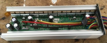
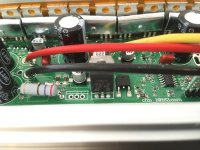
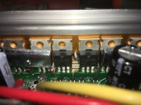
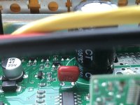
Currently I have the following components (see pics):
- k150e09ne mosfets (Vmax = 85V)
- 470uF 63V capacitors
- 104J 100V metal film capacitors (red capacitors)
- LM317T voltage regulator + 260 Ohm resistor
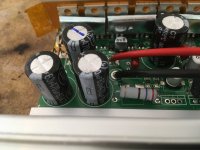
I want to enable the use of a 20s 84V battery. Are these the correct upgrades to do, or do I need to do more:
- Change mosfets to IRFB4110 (Vmax = 100V)
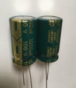
- Change caps to 1000 uF 100V (see pic)
- change red capacitors to 104J 400V 10mm ones (are these the correct ones (V and J)? does size matter here?)
- change LM317T + resistor for a DC-DC buck converter from 20V -> 15V (where does the 20V input come from? does it stay 20V when I provide 72V instead of 48V? Where do I need to connect the 15V output of the buck converter?)
- use a 72V -> 48V buck converter to supply a seperate 48V power supply to the KT-LCD3 and the Bluetooth dongle (is this really necessary? and is this enough to protect both the display and the dongle?)
- edit: do I need to do something with the 78L05 voltage regulator as well (did not find that one yet on the PCB), or is this one already safe if I supply 15V through the buck converter instead of the output of the LM317T + resistor?
Are there any other components that I need to swap or change? Is the rest of the controller capable of handling the 72v/84V input voltage?
I see many people with similar questions about voltage tune-up. But not a complete overview of all necessary steps and components. So a little help would be highly appreciated!
Thanks in advance!
I've been reading through this forum; the work everybody did is absolutely great. But I cannot find a definitive answer on the following question: what exactly do you need to modify to make a 18fet 48v kt controller with a 48v KT3 display and a 48v bluetooth dongle work at 20s 84v max?
Currently I have the following components (see pics):
- k150e09ne mosfets (Vmax = 85V)
- 470uF 63V capacitors
- 104J 100V metal film capacitors (red capacitors)
- LM317T voltage regulator + 260 Ohm resistor
I want to enable the use of a 20s 84V battery. Are these the correct upgrades to do, or do I need to do more:
- Change mosfets to IRFB4110 (Vmax = 100V)
- Change caps to 1000 uF 100V (see pic)
- change red capacitors to 104J 400V 10mm ones (are these the correct ones (V and J)? does size matter here?)
- change LM317T + resistor for a DC-DC buck converter from 20V -> 15V (where does the 20V input come from? does it stay 20V when I provide 72V instead of 48V? Where do I need to connect the 15V output of the buck converter?)
- use a 72V -> 48V buck converter to supply a seperate 48V power supply to the KT-LCD3 and the Bluetooth dongle (is this really necessary? and is this enough to protect both the display and the dongle?)
- edit: do I need to do something with the 78L05 voltage regulator as well (did not find that one yet on the PCB), or is this one already safe if I supply 15V through the buck converter instead of the output of the LM317T + resistor?
Are there any other components that I need to swap or change? Is the rest of the controller capable of handling the 72v/84V input voltage?
I see many people with similar questions about voltage tune-up. But not a complete overview of all necessary steps and components. So a little help would be highly appreciated!
Thanks in advance!
Attachments
tenten8401
1 mW
- Joined
- Aug 22, 2020
- Messages
- 16
sylvain_wm said:In addition to this, is the retrofitting only available for the open source firmware? I'd like to run it but after I ordered I realized it said that LCD8H isn't compatible at all due to a missing clock or something..
Hi tenten8401,
Where did read that the LCD8H doesn't work? Could you send the link?
I have a LCD8H with KT controller, and it seems to work except the 6kph assistant without PAS.
Have a good one
Regards
It works fine on stock but it doesn't work with the open source firmware this thread is about
stancecoke
1 MW
tenten8401 said:It works fine on stock but it doesn't work with the open source firmware this thread is about
is this your personal experience? I know, that there are new "L"-parameters, but I don't know how they are implemented in the communication protocol.
http://www.szktdz.com/upload/file/20181102/20181102083637_12550.pdf
Can you post a log of the bytes sent by the display?
regards
stancecoke
tenten8401
1 mW
- Joined
- Aug 22, 2020
- Messages
- 16
stancecoke said:tenten8401 said:It works fine on stock but it doesn't work with the open source firmware this thread is about
is this your personal experience? I know, that there are new "L"-parameters, but I don't know how they are implemented in the communication protocol.
http://www.szktdz.com/upload/file/20181102/20181102083637_12550.pdf
Can you post a log of the bytes sent by the display?
regards
stancecoke
I don't actually have the kit with me yet, but I remember seeing a forum post at some point that said it didn't work at all on the open firmware for them.. I have no idea on the specifics yet.. Is it working for you on the open source firmware or anyone else that you can find? I just don't want to take the one-way trip only to make my LCD8H useless
I don't even know where I saw that it didn't work and the entire thing does sound kinda confusing to begin with since it connects to the same header on closed firmware, so I'd be willing to give it a go (when my kit arrives a couple weeks from now) if I can just get some confirmation it works.
I'm getting a newer firmware revision because the layout looks different from what I see online:

sylvain_wm
100 mW
- Joined
- Feb 2, 2020
- Messages
- 47
Hi, my LCD8H works with the open source firmware this thread is about.It works fine on stock but it doesn't work with the open source firmware this thread is about
Everything seems to work.
But, as I said, when I hold the "DOWN" button, the meter assist function logo flashes, but the function doesn't work. The motor isn't powered...
I don't have the newer firmware revision on my display.
Regards
Similar threads
- Replies
- 129
- Views
- 47,408
- Replies
- 2
- Views
- 3,630