You are using an out of date browser. It may not display this or other websites correctly.
You should upgrade or use an alternative browser.
You should upgrade or use an alternative browser.
KT motor controllers -- Flexible OpenSource firmware for BMSBattery S/Kunteng KT motor controllers (0.25kW up to 5kW)
- Thread starter casainho
- Start date
stancecoke
1 MW
Strange, but then the 2.6V have to come from "outside"?! Can you check the resistance from these pins to gnd?shellton said:AT STM8 pins 20-22
regards
stancecoke
stancecoke
1 MW
Yes, is there anybody who has the firmware working with a 9FET?
regards
stancecoke
regards
stancecoke
I measured resistance on pins 20-23 and GND - 3.3K . Then i cut the line to pin 20 . To cpu side ~7M , to resistors 3.3K
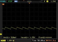
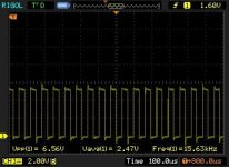
Tryed to get diagram on cutted pin20 :

Strange signal ..
Can it be something wrong with CPU or pin output not initialized properly ? How to find it out ?
As on schematic PIN 19 (PB3) is unused . Can it be assigned for testing ?
Br , Linas
Tryed to get diagram on cutted pin20 :

Strange signal ..
Can it be something wrong with CPU or pin output not initialized properly ? How to find it out ?
As on schematic PIN 19 (PB3) is unused . Can it be assigned for testing ?
Br , Linas
Hello im new here can someone pls tell me how this works? will st link v2 work? how to connect st link? i have kt48zwsrl-xfc15 48v 35a controller.
controller board https://gyazo.com/71cf0bea71c695e0a4e06cb639ab2413
cortroller wires https://gyazo.com/742dd81028d49db1a7868afa50ef169a
controller board https://gyazo.com/71cf0bea71c695e0a4e06cb639ab2413
cortroller wires https://gyazo.com/742dd81028d49db1a7868afa50ef169a
shellton said:Look here :
https://github.com/stancecoke/BMSBattery_S_controllers_firmware/wiki/01-Hardware-needed
CPU is STM8S105 ?
Thank you
stancecoke
1 MW
Hm, seems that the mikrocontroller is defective. 3.3K is OK.shellton said:I measured resistance on pins 20-23 and GND - 3.3K . ...
Can it be something wrong with CPU or pin output not initialized properly ? How to find it out ?
you can disable the PWM output and toggle the pin manually in slow loop to check it.
TIM1_CtrlPWMOutputs(DISABLE);
GPIO_WriteReverse(GPIOx, GPIO_PIN_y);
regards
stancecoke
stancecoke
1 MW
shellton said:I studied source to find out , where i can insert this.
just paste both commands at line 192 of the main.c
regards
stancecoke
Hi , sorry for late answer.
At last i figured out this case. I think it was my faulty. It was something wrong with firmware compiling. I downloaded source one more time and compiled it. And miracle happened , PWM appeared at both : Low and High side . I attached the motor, some angle adjustment and motor started spin perfectly.
What about reverse ? Is it possible to implement ? On pad X4 may be ?
BR , Linas
Black6spdZ
1 W
so I spent all night messing with this KT 18-fet 72v controller only to be defeated. To start I just finished putting my bike back together after sitting in pieces for years. upgraded the original 48/1000 hub motor with larger wires, skf bearings and some statoraid. I did test the halls prior to final assembly "5v-0v" on each one with a magnet. With original KT firmware i kept gettings 03_info error no matter what combination of phase or hall sensor. so I tossed on a sunwin controller and it runs perfect with that controller.. even has speed boost on "high" speed selection which needs hall sensors even though it will run sensorless but no boost.. I verfied this by running with and without hall connections. I decidied to go for broke and see if the opensource firmware may make a difference.. after finally getting the software needed for it I was able to compile and flash as well as get bluosec functioning correctly. But still no spin.. the motor will twitch then lock in place until power is disconnected. I pulled up the phase monitor in bluosec and it just goes between a full circle of 3 and 4. I do not understand how the halls are bad when they test good with a meter.. what am I missing?
stancecoke
1 MW
shellton said:What about reverse ? Is it possible to implement ? On pad X4 may be ?
Yes, of course. You just have to swap two pwm channels and change the angle interpolation. You have to check two following hall events to detect the direction and adapt the angle corresponding. I did it in the Lishui project just two weeks ago
regards
stancecoke
stancecoke
1 MW
The Halls are not in 120° positionBlack6spdZ said:I do not understand how the halls are bad when they test good with a meter.. what am I missing?
If you get only 3 and 4 all three halls are switching at the same time
3 - - > 011
4 - - > 100

regards
stancecoke
Black6spdZ
1 W
stancecoke said:The Halls are not in 120° positionBlack6spdZ said:I do not understand how the halls are bad when they test good with a meter.. what am I missing?
If you get only 3 and 4 all three halls are switching at the same time
3 - - > 011
4 - - > 100

regards
stancecoke
thanks for the reply back. my motor is an old 9C 2706, 46 magnets, 51 poles.. are you saying it is still a potential hardware issue or just software configuration? I'd really like to get this newer controller with sine and regen over the caveman sunwin
quick update.. so when I connect the halls with a 10k pull-up to my two channel scope I get the normal pattern, the same as I see connected to the sunwin, but when I connect the scope to the KT I get the halls turning on for a shorter interval with never any overlap.. wth?
not sure why but continuity on KT hall input between + to sensor is ~46k and sensor to - is ~2.8k whereas the sunwin is 2.8M and 4k
there definately is some hardware issue or compatibilty problem with these halls and the KT..any resistor trickery I could do to make it work?
Look at schematic. Hall sensors must go to PINS 38-40 of CPU.
https://opensourceebikefirmware.bitbucket.io/development/EmbeddedFiles/32-BMSBattery_S06S-Kuteng_EBike_motor_controller_schematic.pdf
If pins are wrong , you can define them in gpio.h
BR , Linas
https://opensourceebikefirmware.bitbucket.io/development/EmbeddedFiles/32-BMSBattery_S06S-Kuteng_EBike_motor_controller_schematic.pdf
If pins are wrong , you can define them in gpio.h
BR , Linas
Black6spdZ
1 W
Its the standard 18-fet PCB.. Maybe they used different value resistors on the supporting circuitry, or maybe a problem with the controller, or maybe the halls in my motor are flaky.. Just not sure how to narrow it down further. The fact that the halls test OK not connected to the KT and work with another controller lead me to believe the motor is OK. But i m not sure if I need another controller or replace the motor halls "which will be a major PITA" at this pointshellton said:Look at schematic. Hall sensors must go to PINS 38-40 of CPU.
https://opensourceebikefirmware.bitbucket.io/development/EmbeddedFiles/32-BMSBattery_S06S-Kuteng_EBike_motor_controller_schematic.pdf
If pins are wrong , you can define them in gpio.h
BR , Linas
stancecoke
1 MW
Do you have an external +5V power supply for the BT-module? The controller internal +5V supply is known to be very weak, it can't handle any additional load. You can try to supply the hallsensors with external +5V, too.Black6spdZ said:I pulled up the phase monitor in bluosec
regards
stancecoke
Trying to review code , to find max ERPMS ;
Do i understand correctly , that max eRPM is 15625/30 and 20833/30 ?
Code:
#define PWM_CYCLES_COUNTER_MAX 3000 // higher values assume motor is at standstill.
#define PWM_CPS_NORMAL_SPEED 15625L
#define PWM_CPS_HIGH_SPEED 20833L
Do i understand correctly , that max eRPM is 15625/30 and 20833/30 ?
Black6spdZ
1 W
stancecoke said:Do you have an external +5V power supply for the BT-module? The controller internal +5V supply is known to be very weak, it can't handle any additional load. You can try to supply the hallsensors with external +5V, too.Black6spdZ said:I pulled up the phase monitor in bluosec
regards
stancecoke
That's what I thought at first so I moved the hall power lead to the 5v pad next to the hall inputs that had a solid 5v but still the same results
Black6spdZ
1 W
ok.. unbelievable.. two of my halls were shorted in the controller connector that looked fine from the exterior. go figure! i had to swap phases wires around but got correct and smooth rotation.. finally! so i've been playing with settings and so far the lowest current freewheel is at 233deg motor angle correction with rotor correction angle on, or 250deg with it off. sine wavetable seems less efficient from a power standpoint with just a slight improvement in audible motor noise. I changed out the rail caps with rubicon 1000uf, 100v instead of the cheap 470uf ones along with a flash pigtail and 10ga power wires. just waiting on some new XT90 connectors to finish up.
on a side note, there is a problem with bluosec app, it's voltage cal only allows up to 100 whereas my 72v controller needs it set to 136. i clicked on it in the app and it changed it to less than 100 again so it looks like i'll have to erase and reflash again to get that right
on a side note, there is a problem with bluosec app, it's voltage cal only allows up to 100 whereas my 72v controller needs it set to 136. i clicked on it in the app and it changed it to less than 100 again so it looks like i'll have to erase and reflash again to get that right
stancecoke
1 MW
I will not implement that, but of course everybody is invited to do it :wink: .Vbruun said:Are there any plans to implement field weakening in this firmware?
It's very easy, you just have to increase the ui8_assumed_motor_position with the speed. You have to do the angle correction procedure later (or earlier, I don't know exacty, just try it...
Code:
if ((ui8_foc_enable_flag) && ((ui8_assumed_motor_position) >= (ui8_correction_at_angle + (ui16_motor_speed_erps>>factor))) &&(ui8_assumed_motor_position) < (ui8_correction_at_angle + (ui16_motor_speed_erps>>factor) + 4))) {
		// make sure we just execute one time per ERPS, so reset the flag
		ui8_foc_enable_flag = 0;

		updateCorrection();
	}
Of course it would be better to activate the additional angle only at very high erps, to keep the best efficieny at lower erps.
regards
stancecoke
Similar threads
- Replies
- 129
- Views
- 46,510
- Replies
- 2
- Views
- 3,595


